Machine tool three-dimensional dynamic cutting force follow-up analog loading device

A loading device and cutting force technology, applied in measuring devices, testing of machine/structural components, instruments, etc., can solve problems such as the inability to measure thermal deformation of machine tools and the inability to install measuring devices, so as to reduce force deformation and improve processing The effect of precision

Active Publication Date: 2015-04-29
江苏中智自动化股份有限公司
View PDF9 Cites 15 Cited by
  • Summary
  • Abstract
  • Description
  • Claims
  • Application Information

AI Technical Summary

Problems solved by technology

However, during the cutting process, the spindle rotates, the feed mechanism moves, and there are chips and cutting fluid in the cutting area, which makes it impossible to install the measuring device and measure the thermal deformation of the machine tool during cutting.
[0005] At present, for the simulated loading of machine tools, the designed device is to disassemble the spindle from the machine tool and apply force to the spindle components separately. The loaded force is also static force. Device for dynamically simulating and loading dynamic cutting force

Method used


Image

  • Machine tool three-dimensional dynamic cutting force follow-up analog loading device
  • Machine tool three-dimensional dynamic cutting force follow-up analog loading device
  • Machine tool three-dimensional dynamic cutting force follow-up analog loading device

Examples


Embodiment Construction

[0028] In order to clarify the technical scheme and technical purpose of the present invention, the present invention will be further introduced below in conjunction with the accompanying drawings and specific implementation methods.

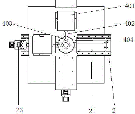
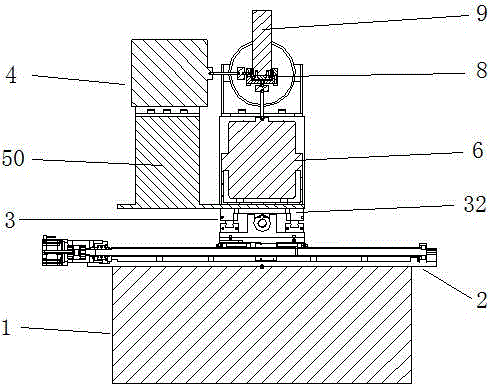
[0029] For the convenience of expression, establish as figure 1 In the X-Y-Z Cartesian coordinate system shown in , the sliding direction of the X-axis sliding pair 3 in the figure is the X-axis, the sliding direction of the Y-axis sliding pair 2 is the Y-axis, and the direction of the axis line of the spindle mandrel 9 is the Z-axis to establish a right angle Coordinate system, the established rectangular coordinate system corresponds to the coordinate system of the machine tool, that is, the sliding direction of the X-axis sliding pair 3 is consistent with the X-axis of the machine tool spindle, and the sliding direction of the Y-axis sliding pair 2 is consistent with the Y-axis of the machine tool spindle , the axis line direction of the spi...


PUM


Abstract

The invention discloses a machine tool three-dimensional dynamic cutting force follow-up analog loading device. The machine tool three-dimensional dynamic cutting force follow-up analog loading device comprises a machine tool working table, a main shaft core rod, a Y-axis sliding pair, an X-axis sliding pair, a bearing system, an L-shaped base plate, a force loading system and a follow-up loading control circuit. The Y-axis sliding pair is fixedly connected with the machine tool working table, the X-axis sliding pair is installed on a sliding block of the Y-axis sliding pair, and the L-shaped base plate is fixedly connected with the X-axis sliding pair. The lower end of the main shaft core rod is connected with the bearing system to bear cutting force analog loading. A Z-axis force loading device is installed at a corner part of the L-shaped base plate, and an output shaft of the Z-axis force loading device is connected with a bearing end cover through a tension and pressure sensor. A Y-axis force loading device and an X-axis force loading device are installed at the two ends of the L-shaped base plate respectively, and output shafts of the Y-axis force loading device and the X-axis force loading device are connected with an outer circular face of a bearing outer base through the tension and pressure sensor. By means of the device, machining errors of a machine tool during cutting machining can be measured, and an analysis platform is provided for measurement and analysis of deformation errors, caused by cutting force, of the machine tool.

Description

technical field [0001] The invention relates to a machine tool simulation loading device, in particular to a machine tool three-way dynamic cutting force simulation loading device for studying the influence of cutting force on the machining accuracy of the machine tool. Background technique [0002] There are many factors that affect machine tool errors. At present, relatively complete identification methods, modeling methods and compensation methods for thermal errors and geometric errors have been obtained. Since high-speed hard cutting and high-power cutting and difficult-to-machine new materials were rarely involved in the past, and the research methods were limited, it is generally believed that the cutting force has little influence on the accuracy of the machine tool and will not be considered. In recent years, with the improvement of machine tool machining accuracy and the development of difficult-to-machine materials, more and more attention has been paid to the mac...

Claims


Application Information

Patent Timeline
Patent Type & Authority Applications(China)
IPC IPC(8): G01M99/00
Inventor 梁睿君赵新洁韩松林叶文华王涛
Owner 江苏中智自动化股份有限公司
Why Eureka
Try Eureka