A gas detection device

A gas detection and gas technology, applied in the field of gas leakage detection, can solve problems such as narrow absorption band, poor contrast, and difficult detection, and achieve the effects of reducing equipment production costs, improving accuracy, and improving observation effects

Active Publication Date: 2017-10-27
SHANGHAI JUGE ELECTRONICS TECH
View PDF6 Cites 1 Cited by
  • Summary
  • Abstract
  • Description
  • Claims
  • Application Information

AI Technical Summary

Problems solved by technology

Take the detection of sulfur hexafluoride gas (SF6) as an example. SF6 is a colorless and odorless gas. It is difficult to detect it with traditional methods and the effect is not good.
Because it has a strong absorption in the infrared band around 10.6 μm, it can be detected by using an infrared camera, but the absorption band of SF6 is very narrow, and it only has obvious absorption in the 10.5 μm ~ 10.7 μm band, while the general The uncooled thermal imager responds to the electromagnetic radiation in the 8μm ~ 14μm band, so the radiation absorbed by SF6 only accounts for a small part of the total radiation received by the thermal imager, which leads to leakage points The difference between the background and the background is very subtle, the contrast is poor, and it is easy to miss
Using some cooling detectors, such as Quantum Well Infrared Photodetector (QWIP, QuantumWell Infrared Photodetector), the response band of the detector can be adjusted so that it only responds to electromagnetic radiation in the vicinity of 10.5 μm to 10.7 μm, thereby improving Detect contrast, but need to customize a special detector for each specific gas, which is inconvenient and expensive to produce

Method used


Image

  • A gas detection device
  • A gas detection device
  • A gas detection device

Examples


Embodiment Construction

[0023] The present invention will be described in further detail below in conjunction with the accompanying drawings.

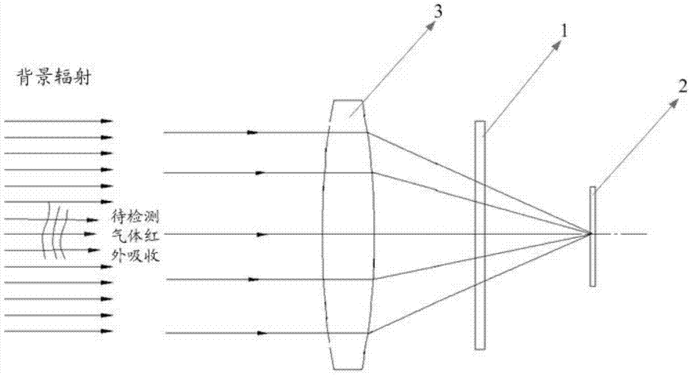
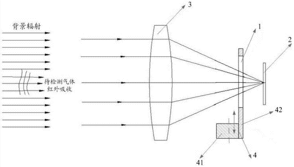
[0024] figure 1 A schematic structural diagram of a gas detection device according to an embodiment of the present invention is shown, wherein the gas detection device includes: an optical filter 1, wherein the transmission band of the optical filter 1 includes the corresponding infrared absorption peak of the gas to be detected wavelength; the uncooled infrared detector 2 is used to acquire and output the infrared imaging information passed through the filter; the infrared lens 3 is used to converge the infrared rays of the object to the uncooled infrared detector 2 .

[0025] Here, the gas to be detected refers to any gas with infrared absorption characteristics, such as sulfur hexafluoride (SF6), ethylene, acetic acid, chlorine dioxide, etc., which have different infrared absorption peak wavelengths, such as the infrared absorption of SF6 The peak wavelen...


PUM

PropertyMeasurementUnit
widthaaaaaaaaaa

Abstract

The object of the present invention is to provide a gas detection device. Specifically, the gas detection device includes: an optical filter, wherein the transmission band of the optical filter includes the corresponding infrared absorption peak wavelength of the gas to be detected; an uncooled infrared detector is used to acquire and output The infrared imaging information of the light sheet; the infrared lens is used to converge the infrared rays of the object to the uncooled infrared detector. Among them, compared with the prior art, the present invention implements a gas detection device by combining an optical filter with an uncooled infrared detector. The beneficial technical effect of the detector as a detector is mainly reflected in no refrigeration, low power consumption, small size, miniaturization, quick start, more convenient to carry, light weight, long service life, low cost, etc.; and the optical path of the present invention not only It is simple and easy to implement, and also reduces equipment production costs and the like.

Description

technical field [0001] The present invention relates to the technical field of gas leakage detection, in particular to the technology of a gas detection device. Background technique [0002] Gas leak detection has always been one of the important topics in industrial production. The traditional method of detecting gas leakage is usually to turn off the equipment first, apply soapy water on the surface of the detection area, and determine the leakage point by observing whether there are bubbles. This method is more laborious and the detection accuracy is not high. The use of spectral imaging to detect gas leaks is a method that has developed rapidly in recent years. We know that according to Planck's law, objects radiate electromagnetic waves all the time at any temperature, so detectors sensitive to certain wavebands can be used to collect The radiation information in these bands is used to image objects. Using this principle, for some special gases, it can be known through...

Claims


Application Information

Patent Timeline
Patent Type & Authority Patents(China)
IPC IPC(8): G01N21/3504G01M3/38G01J5/08
Inventor 赵高飞吴建华沈憧棐
Owner SHANGHAI JUGE ELECTRONICS TECH
Why Eureka
Try Eureka