
Method for determining polycrystalline metal deformation activation slippage system

A polycrystalline metal and slip technology, which is applied in the direction of measuring devices, instruments, and material analysis through optical means, can solve the inconvenience of orientation information corresponding to the grain position and damage morphology, the inability to determine the slip system, and the inability to realize Analysis of crystal orientation and damage morphology etc.

Inactive Publication Date: 2015-04-29
DALIAN UNIV OF TECH
View PDF2 Cites 11 Cited by
  • Summary
  • Abstract
  • Description
  • Claims
  • Application Information

AI Technical Summary

Problems solved by technology

Among them, the first three are based on the estimation of the theoretical slip system based on the size of the Schmid factor, and the actual slip system cannot be determined; the orientation information obtained by the X-ray diffraction method is inconvenient to correspond to the grain position and damage morphology. For the orientation analysis of single crystal materials; the transmission electron microscopy method needs to destroy the sample during the sample preparation process, and can only obtain the orientation information of limited micro-regions, and it is almost impossible to analyze the crystal orientation and damage morphology in the area range
In this case, it becomes very difficult to accurately determine the deformation-activated slip system of polycrystalline metal materials

Method used


Image

  • Method for determining polycrystalline metal deformation activation slippage system
  • Method for determining polycrystalline metal deformation activation slippage system
  • Method for determining polycrystalline metal deformation activation slippage system

Examples


Embodiment Construction

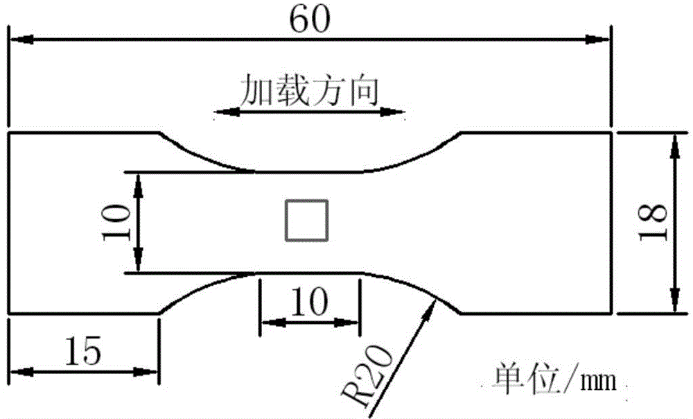
[0020] Step 1. Cut the Z2CND18.12N austenitic stainless steel wire into a thin sheet sample with a thickness of 1.8mm, such as figure 1 shown. Firstly, the surface of the sample was mechanically polished, from 200# sandpaper to 1000# sandpaper, then polished with a diamond abrasive paste with a particle size of 1.5 μm, and finally vibrated on a Buller Vibrome-2 vibration polishing machine for 2 hours to remove the residual stress on the surface. Prepare for subsequent EBSD analysis.

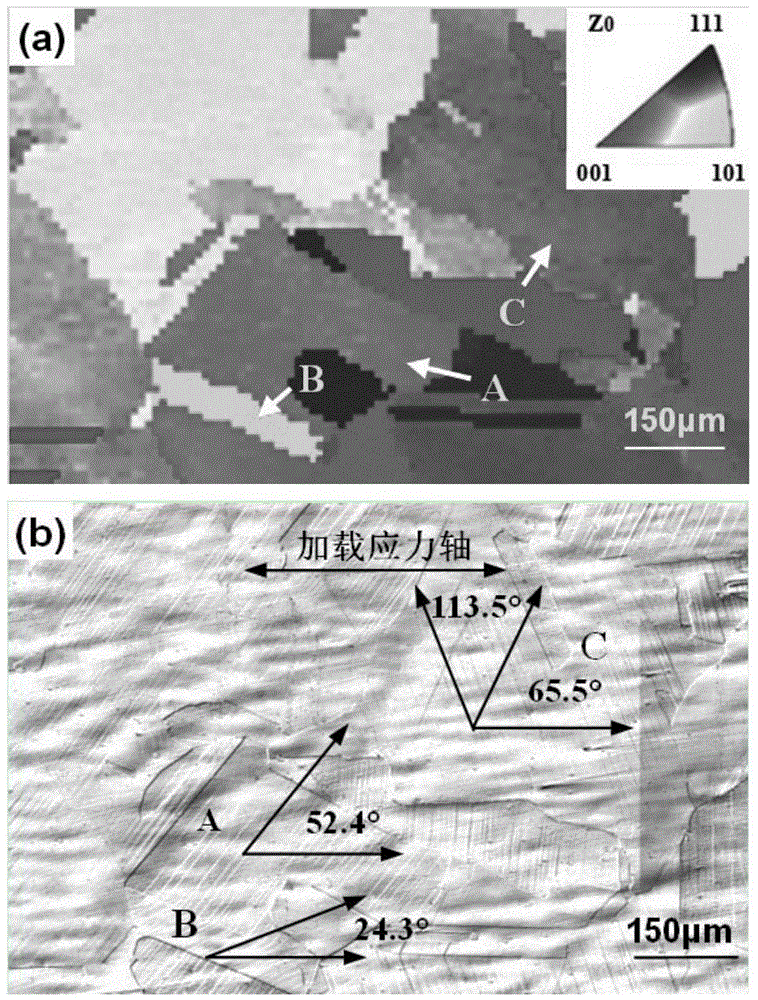
[0021] Step 2. Analyze the crystal orientation of the parallel segment region on a Zeiss Supra 55 field emission scanning electron microscope and an Oxford EBSD analyzer. The test step size is 10 μm, the magnification is 200×, and the crystal orientation distribution of a certain number of grains is obtained, such as figure 2 (a), where the crystal orientation indices of the three grains A, B, and C are [104], [516], and [235], respectively, and the orientation indices in the direction of the ...


PUM


Abstract

The invention provides a method for determining a polycrystalline metal deformation activation slippage system and belongs to the field of analysis of a material mechanical property. The method comprises the following steps: carrying out crystal orientation analysis on the surface of a test sample by adopting an EBSD analyzer; analyzing a loaded slippage band appearance by adopting a laser co-focusing microscope; calculating an included angle between a slippage band and a loading stress axis and comparing with an actual measurement value to determine a slippage surface; calculating a Schmid factor of a possible slippage system corresponding to the slippage surface; and determining a slippage direction according to a Schmid principle. Existing analysis methods mainly comprise five methods including an accrual method, a diagrammatizing method, a tensile axis index observation method, an X-ray diffraction method and a transmission electron microscope method. The first three methods are used for speculating a theoretical slippage system, and cannot be used for determining an actual activation slippage system; and the last two methods cannot be used for analyzing crystal orientation and damage appearance at the same time. The method can be used for analyzing the orientation of grain crystals and the corresponding slippage band appearance, and is relatively suitable for activation slippage system analysis after polycrystalline metal mechanical deformation.

Description

technical field [0001] The invention relates to a method for determining the deformation-activated slip system of polycrystalline metal, which belongs to the field of material mechanical property analysis. Background technique [0002] Once the slip surface of polycrystalline metal slips along the slip direction under the action of external load, it will interact with the free surface of the sample to form a slip zone. At this time, the corresponding slip system is considered to be activated, and the corresponding slip The plane and slip directions are denoted by facet index and orientation index, respectively. Determining the slip system is of great significance for elucidating the mechanical deformation mechanism of materials and evaluating the service performance of materials. [0003] How to accurately determine the active slip system is a major problem in the analysis of material mechanics. Relevant researchers have successively reported five methods including accumul...

Claims


Application Information

Patent Timeline
Patent Type & Authority Applications(China)
IPC IPC(8): G01N23/203G01N21/00
Inventor 罗忠兵齐赫杨林莉周全邹龙江
Owner DALIAN UNIV OF TECH
Learn More