An in-situ detection method for the phase transition process of crystalline polymers

A crystalline polymer and in-situ detection technology, which is applied in the detection field, can solve the problems of complex structure of detection devices, cumbersome operation methods, and difficulty in realization, and achieve the effects of fast detection steps, accurate detection results, and simple devices

Inactive Publication Date: 2017-09-01
ANHUI UNIVERSITY
View PDF8 Cites 0 Cited by
  • Summary
  • Abstract
  • Description
  • Claims
  • Application Information

AI Technical Summary

Problems solved by technology

The structure of these detection devices is very complicated, the purchase cost is high, and the actual operation method of some devices is relatively cumbersome.
For example, when using X-ray diffraction method and polarizing microscope to detect the degree of phase transition, these two methods have a large workload and cannot be continuously and quantitatively tested
In addition, the compression and sample preparation of the polarizing microscope are difficult; the measurement method of the infrared measurement method when the sample reaches melting is difficult to handle, so although this method is theoretically feasible, it is not easy to implement in practice
Differential scanning calorimetry is usually only used to detect the phase transition process of isothermal crystallization and non-isothermal, isothermal crystallization process, and the cost is relatively high
[0004] In the actual processing operation, the phase transition process of crystalline polymers is mostly under the condition of non-isothermal and non-constant-rate cooling. As for the phase transition behavior of crystalline polymers under non-isothermal and non-constant-rate conditions, there is still a lack of low-cost, simple , fast detection method

Method used


Image

  • An in-situ detection method for the phase transition process of crystalline polymers
  • An in-situ detection method for the phase transition process of crystalline polymers
  • An in-situ detection method for the phase transition process of crystalline polymers

Examples


Embodiment 1

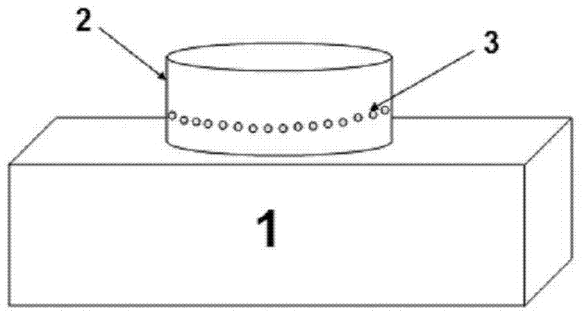
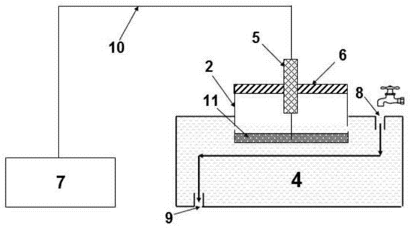
[0030] Schematic diagram of the structure of the in-situ detection device for the phase transition process of the crystalline polymer described in the present invention is as follows figure 1 , figure 2 shown.

[0031] The device includes two parts, namely a heating device and an in-situ testing device. The heating device includes a programmed temperature control heating table 1 and a specially designed metal container 2, the metal container 2 is a cylindrical stainless steel container with a radius of 20 mm and a height of 10 mm, and the metal container 2 is 4 mm away from the bottom. Thirty circular holes 3 with a radius of 0.75 mm are opened on the wall to allow cooling water to enter the metal container 2 to cool the polymer melt 11 . The in-situ test device includes the metal container 2 , a water tank 4 , a T-type thermocouple 5 , a fixing device (fixture) 6 and a temperature digital display 7 . A water inlet 8 is provided on the upper right of the water tank 4, and ...

Embodiment 2

[0042] Schematic diagram of the structure of the in-situ detection device for the phase transition process of the crystalline polymer described in the present invention is as follows figure 1 , figure 2 shown.

[0043] The device includes two parts, namely a heating device and an in-situ testing device. The heating device includes a programmed temperature control heating table 1 and a specially designed metal container 2, the metal container 2 is a cylindrical stainless steel container with a radius of 20 mm and a height of 10 mm, and the metal container 2 is 4 mm away from the bottom. Thirty circular holes 3 with a radius of 0.5 mm are opened on the wall to allow cooling water to enter the metal container 2 to cool the polymer melt 11 . The in-situ test device includes the metal container 2 , a water tank 4 , a T-type thermocouple 5 , a fixing device (fixture) 6 and a temperature digital display 7 . A water inlet 8 is provided on the upper right of the water tank 4, and a...

Embodiment 3

[0054] Schematic diagram of the structure of the in-situ detection device for the phase transition process of the crystalline polymer described in the present invention is as follows figure 1 , figure 2 shown.

[0055] The device includes two parts, namely a heating device and an in-situ testing device. The heating device includes a programmed temperature control heating table 1 and a specially designed metal container 2, the metal container 2 is a cylindrical stainless steel container with a radius of 20 mm and a height of 10 mm, and the metal container 2 is 4 mm away from the bottom. Thirty circular holes 3 with a radius of 1.0mm are opened on the wall to allow cooling water to enter the metal container 2 to cool the polymer melt 11 . The in-situ test device includes the metal container 2 , a water tank 4 , a T-type thermocouple 5 , a fixing device (fixture) 6 and a temperature digital display 7 . A water inlet 8 is provided on the upper right of the water tank 4, and a ...


PUM

PropertyMeasurementUnit
radiusaaaaaaaaaa

Abstract

The invention relates to an in-situ detection method for the phase transition process of a crystalline polymer. The device used in the method includes two components, namely a heating device and an in-situ testing device. The heating device includes a programmable temperature control heating table 1 and a specially designed metal container 2, and a series of round holes 3 are equally spaced on the wall of the metal container 2 at a distance of 4 mm from the bottom. The in-situ test device includes the metal container 2, the water tank 4, the thermocouple 5, the fixing device 6 and the temperature digital display 7. The water tank 4 is provided with a water inlet 8 on the upper right, and a water outlet 9 on the lower left. A compensation wire 10 connecting the thermocouple 5 and the temperature digital display 7 is arranged between the thermocouple 5 and the temperature digital display 7 . The fixing device 6 is located directly above the water tank 4 . The invention is especially suitable for the in-situ test of the non-isothermal and non-constant velocity phase transition behavior of the crystalline polymer, and has the advantages of simple device, accurate detection result, low cost, fast detection steps and the like.

Description

technical field [0001] The invention relates to a detection method, in particular to a simple, fast and accurate in-situ detection method for the phase transition process of crystalline polymers. Background technique [0002] Phase change energy storage material (PCM) is a material with energy storage function. Using the characteristics of heat storage and heat release of phase change materials, it can be used in the aviation field, solar energy, and industrial waste heat storage. It can also be used as a temperature control material in Electronics, construction and other industries have broad market application prospects. For some polymer material products, they are usually used under high temperature conditions, so it is very necessary to determine their phase transition temperature when testing product performance. The actual production process of polymer materials, such as extrusion, injection molding, blow molding, etc., is usually completed under dynamic non-isotherma...

Claims


Application Information

Patent Timeline
Patent Type & Authority Patents(China)
IPC IPC(8): G01N25/12
Inventor 杨斌夏茹钱家盛邓艳丽鲁非雪陈鹏苏丽芬胡磊
Owner ANHUI UNIVERSITY
Why Eureka
Try Eureka