A Laser Compensation Method for Compressed Field Plane Wave High Frequency Detection Phase Line Detection

A linear detection and compensation method technology, applied in the phase angle between voltage and current, measuring device, measuring electrical variables and other directions, can solve the problems of deterioration of technical indicators, difficult to achieve detection, phase measurement errors, etc. Effect of Plane Wave Phase Detection Accuracy

Active Publication Date: 2018-02-02
BEIJING INST OF RADIO METROLOGY & MEASUREMENT
View PDF2 Cites 0 Cited by
  • Summary
  • Abstract
  • Description
  • Claims
  • Application Information

AI Technical Summary

Problems solved by technology

[0003] The current problem is that when the high-frequency performance of the phase is tested, if the mechanical plane of the probe installed on the scanning frame deviates from the phase plane such as the plane wave, it will cause a large error in the phase measurement. more pronounced when increasing
However, after the scanning frame is used many times, its own technical indicators will seriously deteriorate, and the detection cross-sectional size range of the compact field can reach 2m to 12m. In such a large area, the straightness index of the straight line trajectory of the probe movement can meet the frequency and wavelength to be measured. The technical requirement of 1% is very difficult to achieve in actual testing

Method used


Image

  • A Laser Compensation Method for Compressed Field Plane Wave High Frequency Detection Phase Line Detection
  • A Laser Compensation Method for Compressed Field Plane Wave High Frequency Detection Phase Line Detection
  • A Laser Compensation Method for Compressed Field Plane Wave High Frequency Detection Phase Line Detection

Examples


Embodiment Construction

[0027] In order to illustrate the present invention more clearly, the present invention will be further described below in conjunction with preferred embodiments and accompanying drawings. Similar parts in the figures are denoted by the same reference numerals. Those skilled in the art should understand that the content specifically described below is illustrative rather than restrictive, and should not limit the protection scope of the present invention.

[0028] A compact field plane wave high-frequency phase line detection laser compensation method, the steps of the method include:

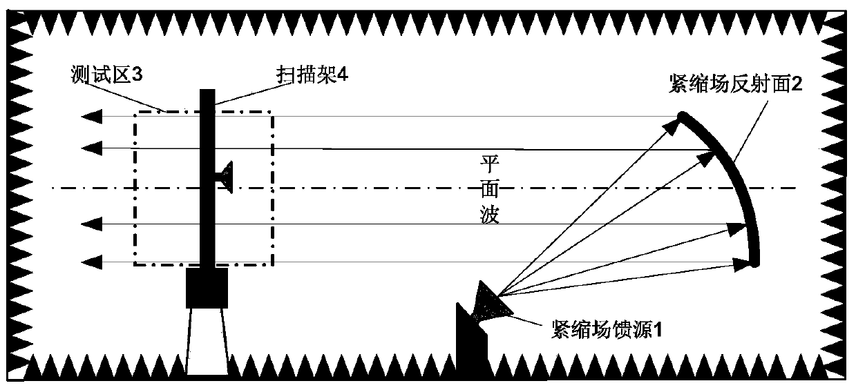
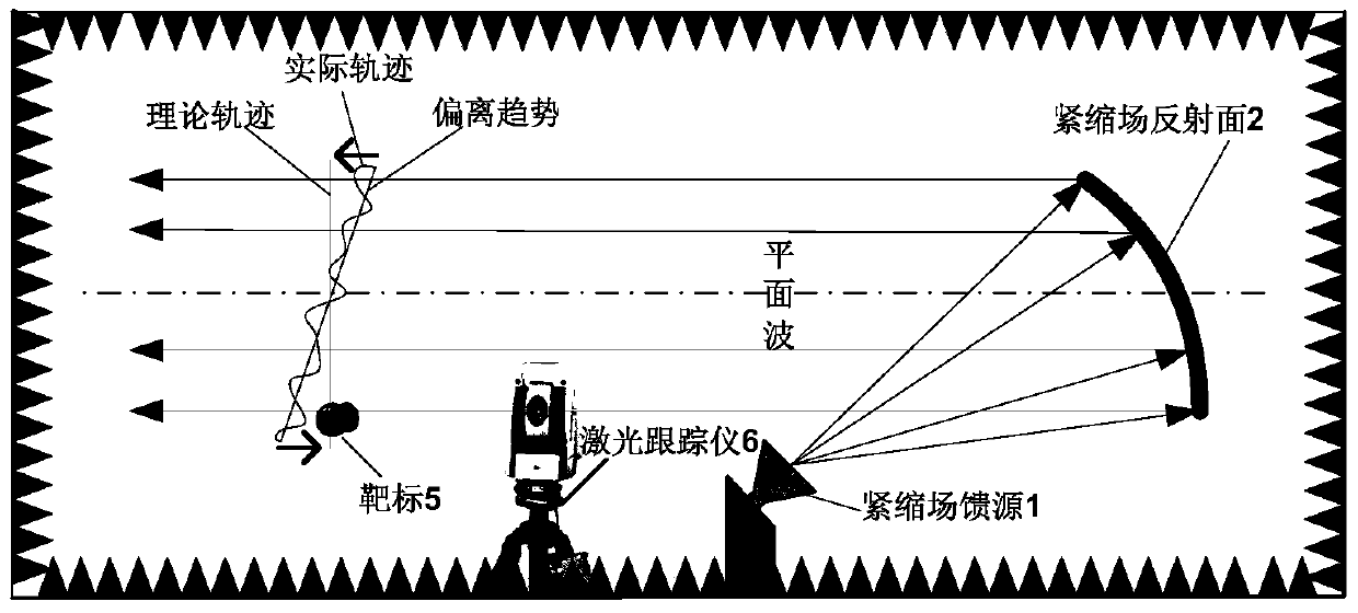
[0029] In the darkroom of the compact field to be inspected, the initial position of the scanning frame 4 is positioned according to the position of the compact field feed source 1, the position of the reflective surface 2 of the compact field, the center of the reflective surface, and the position of the test area 3 through the laser tracker 6 ;

[0030] Use the phase test system to initiall...


PUM


Abstract

The invention discloses a method for establishing a three-dimensional rectangular coordinate system in the darkroom of the compact field to be inspected; determining the initial position of the scanning frame according to the positional relationship between the position of the feed source, the position of the reflecting surface and the test area; and determining the vertical and horizontal attitude angles of the scanning frame. Adjust the phase detection trend to meet the performance requirements of the plane wave; set a laser target on the probe antenna of the scanning frame, and set a laser tracker between the scanning frame and the reflecting surface, and capture the position of the laser target in real time through the laser tracker to obtain a scan The position information and position deviation △x of the frame; according to the speed of light, operating frequency and phase relationship, the phase deviation result of the plane wave is obtained, and the deviation result is compensated into the phase detection result in real time, which can meet the high-frequency compressed field plane wave phase detection Requirements to improve the phase detection accuracy of the compact field plane wave.

Description

technical field [0001] The invention relates to a laser compensation method for high-frequency detection of a compressed field plane wave, phase line detection, and detection. Background technique [0002] Due to its high measurement accuracy and convenient use, the compact field has become a necessary equipment for high-precision measurement of radar target RCS characteristics, seeker tracking, stealth material performance, high-performance radar antenna and radome characteristics, etc. The compact field adopts a precise reflective surface, which can convert the spherical wave generated by the point source into a plane wave at a short distance. The most core index for evaluating the performance of the plane wave in the test area of ​​the compact field is the phase irregularity of the plane wave field. For the measurement of phase roughness, the most commonly used method at present is to set up a scanning frame in the test area, so that the scanning track of the scanning fra...

Claims


Application Information

Patent Timeline
Patent Type & Authority Patents(China)
IPC IPC(8): G01R25/00
Inventor 马永光康宁尚柱岗韩玉峰
Owner BEIJING INST OF RADIO METROLOGY & MEASUREMENT
Why Eureka
Try Eureka