Method for manufacturing fiber ribbon cable
A manufacturing method and technology of optical fiber ribbons, which are applied in the directions of light guides, optics, optical components, etc., can solve problems such as the inability to meet the requirements of cost saving and cost reduction.
- Summary
- Abstract
- Description
- Claims
- Application Information
AI Technical Summary
Problems solved by technology
Method used
Image

Examples
Embodiment 1
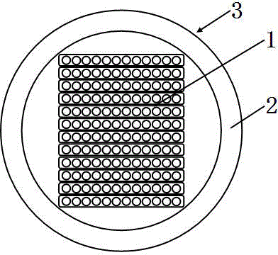
[0064] please see Figure 7 , and refer to Figures 1 to 6 , an optical fiber ribbon cable, which consists of a loose tube 3, a water-blocking layer 4 outside the loose tube, an armor layer 6 outside the water-blocking layer, two strengthening members 5 outside the armor layer, and The outer sheath 7 covered by the armor layer and the strengthening member is composed of an outer sheath 7; it is characterized in that the loose tube 3 includes an optical fiber ribbon body and a loose tube body 2 that covers the optical fiber ribbon body, and the optical fiber The ribbon body is composed of an optical fiber ribbon laminate and optical fiber ribbons 1 located on the left and right sides of the optical fiber ribbon laminate. The optical fiber ribbon laminate is formed by stacking multiple optical fiber ribbons 1 up and down in sequence; The apex of the rectangle is in contact with the inner wall of the loose tube body or has a slight gap; the length of the optical fiber ribbon is ...
Embodiment 2
[0066] please see Figure 8 , and refer to Figures 1 to 6 , an optical fiber ribbon cable, which consists of a loose tube 3, a water-blocking layer 4 outside the loose tube, an armor layer 6 outside the water-blocking layer, four reinforcements 5 outside the armor layer, and the armor The outer sheath 7 covered by the coating layer and the strengthening member is composed of an outer sheath 7; it is characterized in that the loose tube 3 includes an optical fiber ribbon body and a loose tube body 2 that wraps the optical fiber ribbon body, and the optical fiber ribbon The body is composed of an optical fiber ribbon laminate and optical fiber ribbons 1 located on the left and right sides of the optical fiber ribbon laminate. The optical fiber ribbon laminate is formed by stacking multiple optical fiber ribbons 1 up and down in sequence; And the apex of the rectangle is in contact with the inner wall of the loose tube body or has a slight gap; the length of the optical fiber r...
Embodiment 3
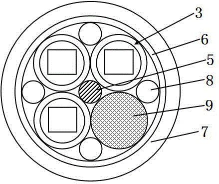
[0085] please see Figure 9 , and refer to the comparison Figure 1 to Figure 6, an optical fiber ribbon cable, which consists of a central strength member 5, four loose tubes 3 distributed outside the strength member in an SZ twisted manner, and peripheral filling ropes 8 located in the outer gaps of adjacent loose tubes 1. The outer sheath 6 covered by the outer filling rope and the loose tube, and the outer sheath 7 coated outside the armor layer by extrusion; the loose tube and the outer filling rope are tangent to the inner edge of the armor layer It is characterized in that the loose tube 3 includes an optical fiber ribbon body and a loose tube body 2 that covers the optical fiber ribbon body, and the optical fiber ribbon body is composed of an optical fiber ribbon laminate and is located on the left and right sides of the optical fiber ribbon laminate. The optical fiber ribbons 1 on both sides are formed, and the optical fiber ribbon laminate is formed by stacking mult...
PUM
 Abstract
Description
Claims
Application Information
 - R&D Engineer
- R&D Manager
- IP Professional
- Industry Leading Data Capabilities
- Powerful AI technology
- Patent DNA Extraction
Browse by: Latest US Patents, China's latest patents, Technical Efficacy Thesaurus, Application Domain, Technology Topic.
© 2024 PatSnap. All rights reserved.Legal|Privacy policy|Modern Slavery Act Transparency Statement|Sitemap