
a liquid crystal display

A liquid crystal display and liquid crystal technology, applied in the direction of instruments, nonlinear optics, optics, etc., can solve the problems of not meeting high transmittance, panel transmittance reduction, color filter substrate aperture ratio reduction, etc.

Active Publication Date: 2018-10-09
NANJING CEC PANDA LCD TECH
View PDF5 Cites 0 Cited by
  • Summary
  • Abstract
  • Description
  • Claims
  • Application Information

AI Technical Summary

Problems solved by technology

However, because the width of the black material is designed to be slightly larger, the light-transmitting area of ​​each pixel color layer on the color filter substrate becomes smaller relative to the pixel electrodes on the drive circuit array substrate, thus causing the color filter The lower aperture ratio of the substrate further reduces the transmittance of the panel, which does not meet the high transmittance requirements of current product specifications

Method used

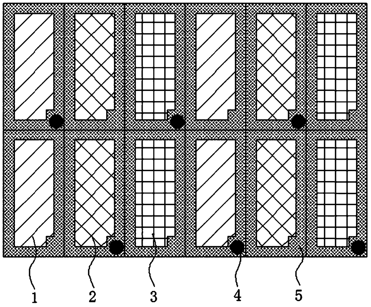
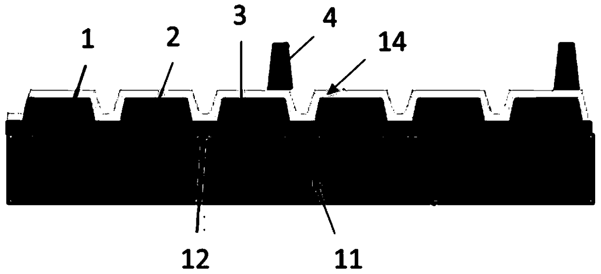

Image

  • a liquid crystal display
  • a liquid crystal display
  • a liquid crystal display

Examples


Embodiment Construction

[0027] Below in conjunction with accompanying drawing and specific embodiment, further illustrate the present invention, should be understood that these embodiments are only for illustrating the present invention and are not intended to limit the scope of the present invention, after having read the present invention, those skilled in the art will understand various aspects of the present invention Modifications in equivalent forms all fall within the scope defined by the appended claims of this application.

[0028] The present invention proposes a new liquid crystal display, including: a color filter substrate, an array substrate, a liquid crystal sandwiched between the color filter substrate and the array substrate, and a backlight located below the array substrate. The color filter substrate includes: a glass substrate The black matrix, the color layer area, the transparent electrode, and the supporting column on the black matrix, the area where the black matrix is ​​locate...


PUM


Abstract

The invention provides a liquid crystal display. Support columns are positioned in opposite light-proof regions of a color film substrate and an array substrate; after a part of light of a backlight source penetrates through a gap between a scanning line and a data line, the support columns shield the light deflecting to an opening area. The liquid crystal display provided by the invention aims at realizing the purpose of shielding the light leaking askant through the support columns shaped as water-retaining walls, so that the width of a black matrix on the color film substrate can be appropriately reduced, and thus the light-proof region formed by the black matrix is narrowed, the area of a color-layer light-pervious region on the color film substrate is increased and the opening rate of the color film substrate and the penetration rate of a liquid crystal display panel are increased. The liquid crystal display accords with the development trends of high brightness, high contrast and high efficiency rate of the liquid crystal display.

Description

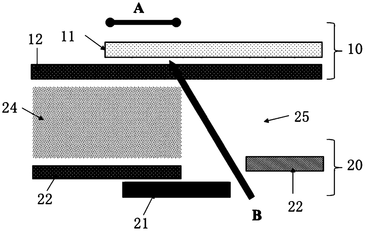
technical field [0001] The invention relates to a liquid crystal display. Background technique [0002] In TFT-LCD, such as figure 1 As shown, the liquid crystal display substrate includes a color filter substrate 10, an array substrate 20, and liquid crystal interposed therebetween, wherein the array substrate 20 is divided into a pixel opening area 24 and an opaque area 25 according to the area, and the opaque area 25 is not transparent. The light areas 25 are distributed around the opening area 24 . On the array substrate 20 , the opening area 24 is a transparent electrode 23 , and the opaque area 25 has scanning lines 21 and data lines 22 , but the widths of the scanning lines 21 and data lines 22 cannot completely cover the opaque area 25 . Correspondingly, on the color filter substrate 10, red, green, and blue layers are distributed in the opening area, and a black matrix 11 made of black material is formed around each red, green, and blue layer to block light leakag...

Claims


Application Information

Patent Timeline
Patent Type & Authority Patents(China)
IPC IPC(8): G02F1/1335
CPCG02F1/133512G02F1/133514
Inventor 李卓林佳玲
Owner NANJING CEC PANDA LCD TECH
Learn More