Current rotating circuit applied to Hall sensor

A Hall sensor and current circuit technology, applied in the electrical field, can solve problems such as interference and MOSFET switch mismatch, and achieve the effects of improving performance, eliminating Hall imbalance, and eliminating the influence of capacitance parasitics

Active Publication Date: 2015-04-29
ZHUHAI ZHONGRUI SCI & TECH CO LTD
View PDF6 Cites 5 Cited by
  • Summary
  • Abstract
  • Description
  • Claims
  • Application Information

AI Technical Summary

Problems solved by technology

[0005] The purpose of the present invention is to solve the problem of MOSFET switch mismatch and parasitic capacitance in the traditional spinning current circuit, and propose a spinning current circuit applied to the Hall sensor, which can eliminate the on-resistance and parasitic capacitance of the MOSFET switch tube in the spinning current circuit Interference, which solves the non-ideal factors of MOSFET switching and the problem of stabilizing the common-mode output voltage of the spinning current circuit in practical applications

Method used


Image

  • Current rotating circuit applied to Hall sensor
  • Current rotating circuit applied to Hall sensor
  • Current rotating circuit applied to Hall sensor

Examples


Embodiment Construction

[0025] The invention will be further described below with reference to the accompanying drawings.

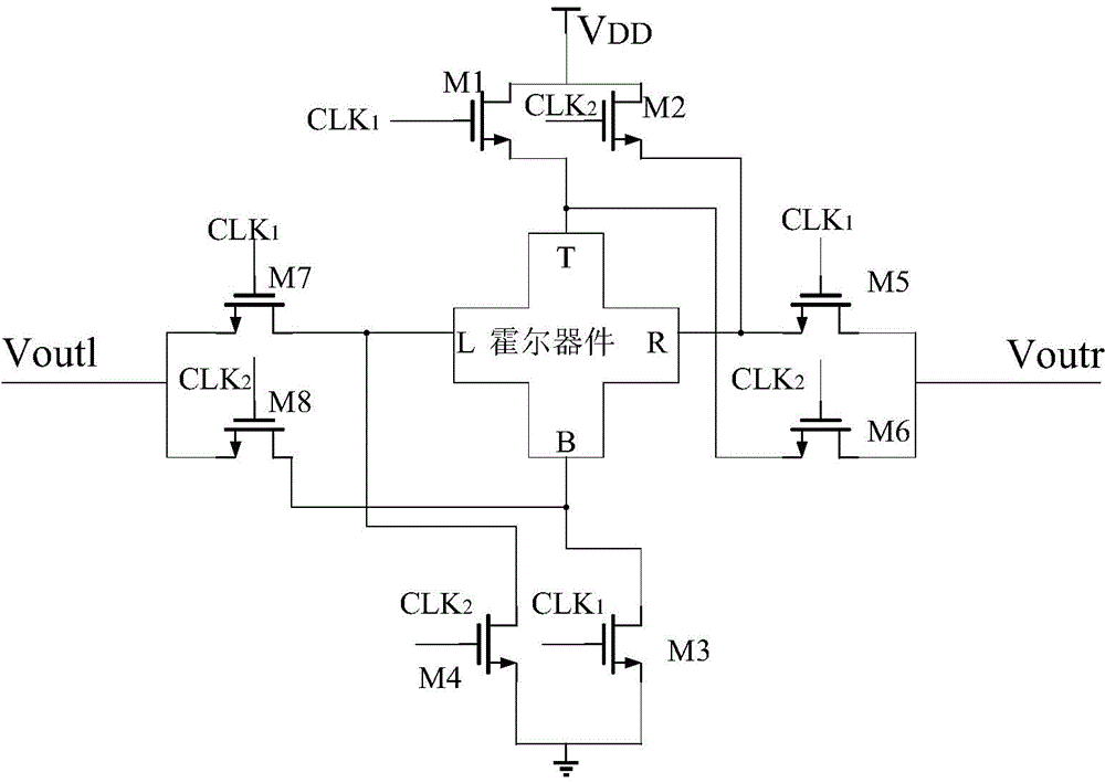
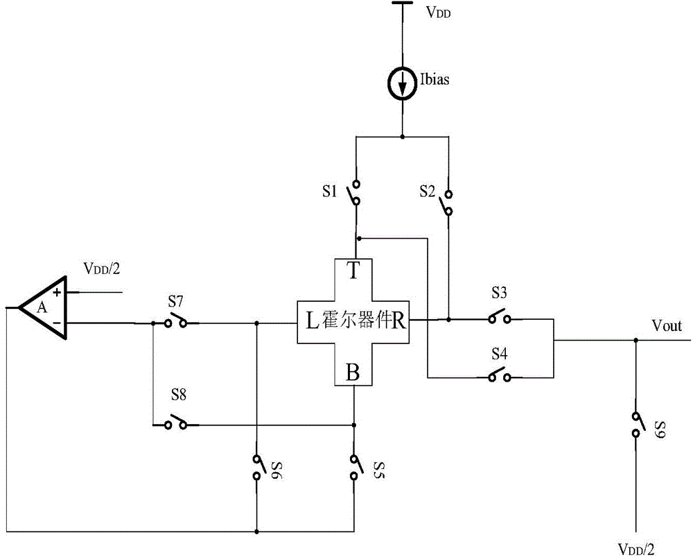
[0026] like image 3 shown and Figure 5 As shown, the rotating current circuit of the present invention is composed of 9 N-channel MOS transistors (ie: M1, M2, M3, M4, M5, M6, M7, M8, M9) and an operational amplifier A. The structure of the circuit is as follows: the drains of the MOS transistors M1 and M2 are connected to the bias power supply, the source of the MOS transistor M1 is connected to the upper port (T) of the Hall device and the source of the MOS transistor M4, and the source of the MOS transistor M2 is connected to The right port (R) of the Hall device and the source of the MOS tube M3; the drains of the MOS tubes M3 and M4 are connected to the output port (Vout) of the circuit and the drain of the MOS tube M9; the sources of the MOS tubes M5 and M6 are connected to The output end of the operational amplifier, the drain of the MOS transistor M5 is connected to t...


PUM


Abstract

The invention discloses a current rotating circuit applied to a Hall sensor. According to the circuit, interference of a turn-on resistance and a parasitic capacitance of an MOSFET (Metal-Oxide-Semiconductor Field Effect Transistor) switching tube in the current rotating circuit on the circuit can be eliminated and an output common-mode voltage of the circuit is stabilized. The circuit has a simple structure and high reliability and can be widely applied to the Hall sensor to carry out current rotation of a Hall signal so as to eliminate detuning. The current rotating circuit disclosed by the invention is mainly applied to an integrated 2D (two-dimensional) Hall sensor.

Description

technical field [0001] The invention relates to a rotating current circuit applied to a Hall sensor, belonging to the technical field of electricity. Background technique [0002] Hall sensor is a magnetic field sensor made according to the Hall effect. Hall devices have many advantages. They are firm in structure, small in size, light in weight, long in life, convenient in installation, low in power consumption, high in frequency, resistant to vibration and not afraid of Pollution or corrosion from dust, oil, water vapor and salt spray. Through it, many non-electric and non-magnetic physical quantities such as force, torque, pressure, stress, position, displacement, speed, acceleration, angle, angular velocity, number of revolutions, rotational speed, and the time when the working state changes, etc. are converted into electricity. Detect and control. [0003] However, the magnetic field sensitivity of the Hall sensor based on silicon technology is low, and the misalignme...

Claims


Application Information

Patent Timeline
Patent Type & Authority Applications(China)
IPC IPC(8): G05F1/56
Inventor 徐跃谢小朋陈小青黄杨
Owner ZHUHAI ZHONGRUI SCI & TECH CO LTD
Why Eureka
Try Eureka