
Transmission coil for magnetically-coupled resonant wireless power transmission system

A resonant radio and transmission coil technology, applied in electromagnetic wave systems, transformers/inductor coils/windings/connections, circuits, etc., can solve problems such as low transmission efficiency, low coil quality factor, and large parasitic capacitance, and achieve unity Good, the quality factor is improved, and the effect of large self-inductance

Inactive Publication Date: 2015-04-29
HARBIN INST OF TECH
View PDF2 Cites 8 Cited by
  • Summary
  • Abstract
  • Description
  • Claims
  • Application Information

AI Technical Summary

Problems solved by technology

[0003] The purpose of the present invention is to solve the problem that the structure of the existing coil has large parasitic capacitance between turns and the quality factor of the coil is low, which leads to low transmission efficiency of the wireless magnetic coupling resonance power transmission system, and now provides a magnetic coupling resonance type radio Transmission coil capable of transmission system

Method used


Image

  • Transmission coil for magnetically-coupled resonant wireless power transmission system

Examples


specific Embodiment approach 1

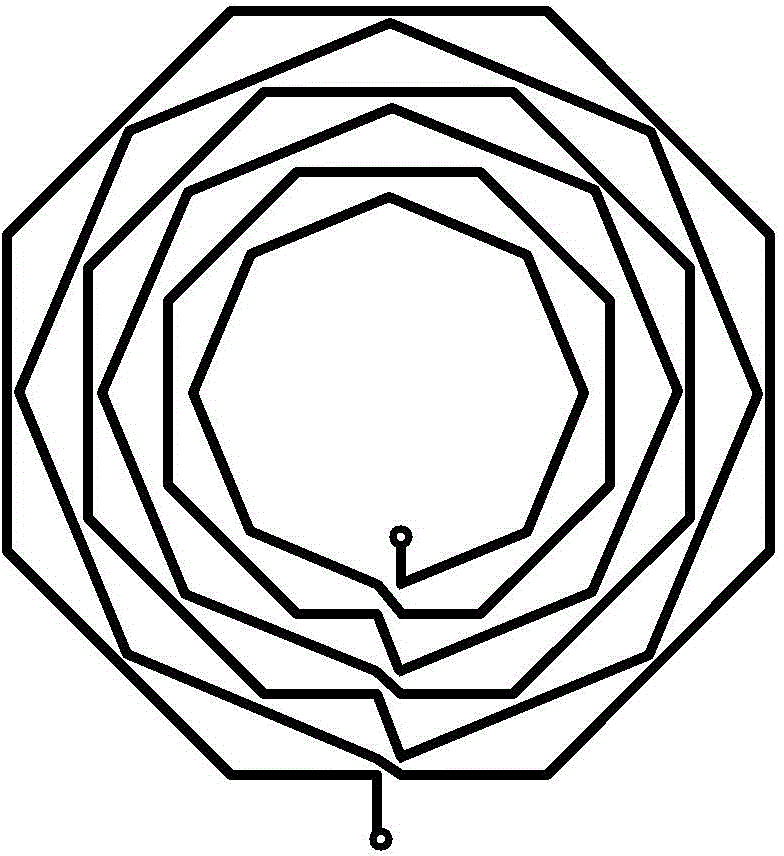
[0010] Specific embodiment one: reference figure 1 To describe this embodiment in detail, a transmission coil for a magnetic coupling resonance wireless power transmission system described in this embodiment includes a multi-turn coil, each turn of the coil is a regular polygon, and the geometry of each turn of the coil The centers are all located at the same point, all the turns of the coils are located on the same plane, and the vertex of any one turn of the polygonal coil is directly opposite to the midpoint of the corresponding side of the adjacent turn.

[0011] The transmission coil used in the magnetic coupling resonance wireless power transmission system described in this embodiment adopts a planar structure, that is, all turns of the coil are located on the same plane, which is convenient for processing in a printed circuit board; It is a polygonal structure, and the adjacent two-turn polygons are angularly misaligned, that is, the vertex of any one-turn polygon is direc...

specific Embodiment approach 2

[0012] Embodiment 2: This embodiment is a further description of a transmission coil used in a magnetic coupling resonance wireless power transmission system described in Embodiment 1. In this embodiment, all turns of the coil have the same winding direction.

specific Embodiment approach 3

[0013] Specific embodiment three: This embodiment is a further description of a transmission coil used in a magnetic coupling resonance wireless power transmission system described in specific embodiments 1 or 2. In this embodiment, any one-turn polygonal coil and phase The coils of adjacent turns are connected end to end.

[0014] The adjacent coils are connected end-to-end, that is, the head end of one turn of the coil is connected to the tail end of the adjacent previous turn, and the tail end is connected to the head end of the next adjacent turn.


PUM


Abstract

The invention belongs to the field of wireless power transmission, relates to a transmission coil for a magnetically-coupled resonant wireless power transmission system and aims to solve the problems that the existing coil structure is high in inter-turn stray capacitance and low in quality factor, thus the wireless magnetically-coupled resonant power transmission system is low in transmission efficiency. The transmission coil is in a planar spiral structure; each turn of the coil is in the shape of a regular polygon; geometric centers of the regular polygons are all at a same point; an apex of the regular polygon of any turn faces the midpoint of the regular polygon of the adjacent turn. The transmission coil is convenient to add to a printed circuit board; inter-turn stray capacitance can be decreased by at least 40% to 80%, heat loss caused by proximity effect and eddy current effect of parallel lines is decreased, the quality factor of the transmission coil is increased by 50%, and transmission efficiency of the wireless magnetically-couple resonant power transmission system is improved. The transmission coil is suitable for the magnetically-coupled resonant wireless power transmission system.

Description

Technical field [0001] The invention belongs to the field of wireless power transmission, and particularly relates to a coil applied to a wireless power transmission system. Background technique [0002] The wireless power transmission system has extremely important research and application value in many fields because of its non-electrical connection power transmission characteristics. In a paper published by Professor Solgasik of Massachusetts Institute of Technology in 2007, the concept of using resonant coils to achieve wireless power transmission was first proposed, and the quality factor of the coil was crucial for high-efficiency power transmission. . For resonant coils for wireless power transmission, the larger the inductance, the smaller the parasitic capacitance, the smaller the internal resistance, and the higher the quality factor. However, the shape of each turn of the existing coil is mostly circular or square. The structure of this type of coil has a large inter...

Claims


Application Information

Patent Timeline
IPC IPC(8): H01F38/14H01F27/28H02J17/00H02J50/12
Inventor 朱春波毛世通魏国逯仁贵宋凯李阳
Owner HARBIN INST OF TECH
Learn More