Array substrate, manufacturing method of array substrate and display device

A technology of an array substrate and a manufacturing method, which is applied in the display field and can solve problems such as short circuit of signal lines and gate lines.

Active Publication Date: 2015-04-29
HEFEI XINSHENG OPTOELECTRONICS TECH CO LTD +1
View PDF4 Cites 21 Cited by
  • Summary
  • Abstract
  • Description
  • Claims
  • Application Information

AI Technical Summary

Problems solved by technology

[0005] The technical problem to be solved by the present invention is to provide an array substrate, its manufacturing method, and a display device. Without increasing the number of patterning processes of the array substrate, it can effectively avoid etching shallow holes and deep holes at the same time due to long-time etching. The oxide semiconductor layer and the gate insulating layer at the shallow hole are etched through, causing the signal line and the gate line to be short-circuited.

Method used


Image

  • Array substrate, manufacturing method of array substrate and display device
  • Array substrate, manufacturing method of array substrate and display device
  • Array substrate, manufacturing method of array substrate and display device

Examples


Embodiment 1

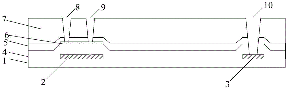
[0054] This embodiment provides a method for manufacturing an array substrate, including the following steps:

[0055] Coating photoresist on the insulating layer covering the conductive pattern or semiconductor pattern;

[0056]Exposure to at least form a photoresist partially reserved area and a photoresist completely removed area, wherein the photoresist partially reserved area corresponds to the area where the first via hole is formed, and the photoresist completely removed area corresponds to the area where the second via hole is formed Specifically, the thickness of the photoresist in the photoresist partially reserved region is smaller than the thickness of the photoresist in the photoresist completely reserved region, and the thickness of the photoresist in the photoresist partially reserved region is greater than that of the photoresist completely removed The thickness of the photoresist in the area;

[0057] Etching, at least partially removing the insulating layer ...

Embodiment 2

[0085] Taking the array substrate as an oxide thin film transistor array substrate as an example, the fabrication method of the array substrate of this embodiment will be described in detail below with reference to the accompanying drawings. Apparently, the described embodiments are only some of the embodiments of the present invention, but not all of them. Based on the embodiments of the present invention, all other embodiments obtained by persons of ordinary skill in the art without making creative efforts belong to the protection scope of the present invention.

[0086] It should be noted that the terms "upper", "lower", "inner" and "outer" in the embodiments of the present invention are only used to describe the embodiments of the present invention with reference to the drawings, and are not used as limiting terms.

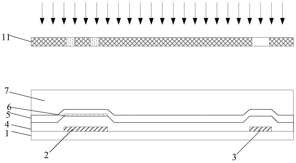
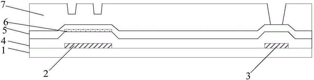
[0087] The manufacturing method of the present embodiment comprises the following steps:

[0088] Step e, such as figure 2 As shown, the photoresist 7 is c...

Embodiment 3

[0115] This embodiment also provides an array substrate, which is manufactured by using the above method for manufacturing an array substrate.


PUM


Abstract

The invention provides an array substrate, a manufacturing method of the array substrate and a display device. The manufacturing method includes the steps that photoresist is coated to an insulating layer covering a conductive pattern or a semiconductor pattern; exposing is carried out to at least form a photoresist partial reserving area and a photoresist complete removing area; etching is carried out to at least partially remove the portion, corresponding to the photoresist complete removing area, of the insulating layer so as to form a middle hole; etching is carried out again to form a first via hole, a second via hole is formed in the position of the middle hole, and the portions, where the first via hole and the second via hole are formed, of the conductive pattern or the semiconductor pattern are exposed, wherein the depth of the first via hole is smaller than the depth of the second via hole. By means of the array substrate, the manufacturing method of the array substrate and the display device, on the premise that the number of times of composition processes of the array substrate is not increased, the condition that when a shallow hole and a deep hole are etched at the same time, an oxide semiconductor layer and a gate insulating layer at the position of the shallow hole are punctured through etching due to long-time etching, so that a single line and a gate line are in short circuit is avoided.

Description

technical field [0001] The present invention relates to the field of display technology, in particular to an array substrate, a manufacturing method thereof, and a display device. Background technique [0002] Oxide TFT (Oxide Thin Film Transistor) is different from the traditional amorphous silicon semiconductor technology, using metal oxide (such as IGZO) as the semiconductor layer. Oxide TFT has the advantages of full transparency, insensitivity to light, increased aperture ratio, improved brightness, reduced power consumption, and high electron mobility, and has become a new favorite in the display field. [0003] However, the metal oxide semiconductor layer has relatively high environmental requirements, and the oxygen and water in the air will affect its characteristics. Therefore, it is necessary to set an ESL (Etch Stop Layer)-etch stop layer on the metal oxide semiconductor layer. like figure 1 As shown, in the prior art, when making an oxide thin film transistor ...

Claims


Application Information

Patent Timeline
Patent Type & Authority Applications(China)
IPC IPC(8): H01L21/84H01L27/12H01L23/50
CPCH01L21/77H01L23/50H01L27/1214H01L27/1288H01L2021/775H01L21/0274H01L21/31144H01L21/76816H01L27/1225H01L27/124H01L29/66969H01L29/7869H01L21/47573H01L21/76802H01L21/84H01L27/12
Inventor 王玉亮崔大永刘增利李道杰陈士娟
Owner HEFEI XINSHENG OPTOELECTRONICS TECH CO LTD
Why Eureka
Try Eureka