A new type of gel power battery terminal post sealing structure

A power battery and terminal post technology, which is applied in the field of battery terminal post sealing structure, can solve the problem that surface roughness and assembly operation deviation cannot be completely sealed, current carrying capacity and high current safety cannot be guaranteed, connection points and Corrosion of related components and other issues, to achieve the effect of enhancing current carrying capacity and high current safety, current carrying capacity and high current safety performance guarantee, and good sealing effect

Inactive Publication Date: 2017-04-26
无锡华燕新电源有限公司
View PDF5 Cites 0 Cited by
  • Summary
  • Abstract
  • Description
  • Claims
  • Application Information

AI Technical Summary

Problems solved by technology

[0002] The current sealing structure of the terminal post of the gel battery is easily affected by a series of unstable factors such as the size deviation of the pole and the rubber ring, the surface roughness, and the deviation of the assembly operation, so that the fit cannot be completely sealed, and the poor sealing of the terminal post will cause acid leakage. , acid climbing phenomenon, and cause corrosion to the connection point and related components, affecting the normal use of the battery. After acid leakage, it must be cleaned up and pollute the environment. The current carrying capacity and high current safety cannot be guaranteed.

Method used


Image

  • A new type of gel power battery terminal post sealing structure
  • A new type of gel power battery terminal post sealing structure

Examples


Embodiment Construction

[0013] The present invention will be further described below in conjunction with the accompanying drawings and embodiments.

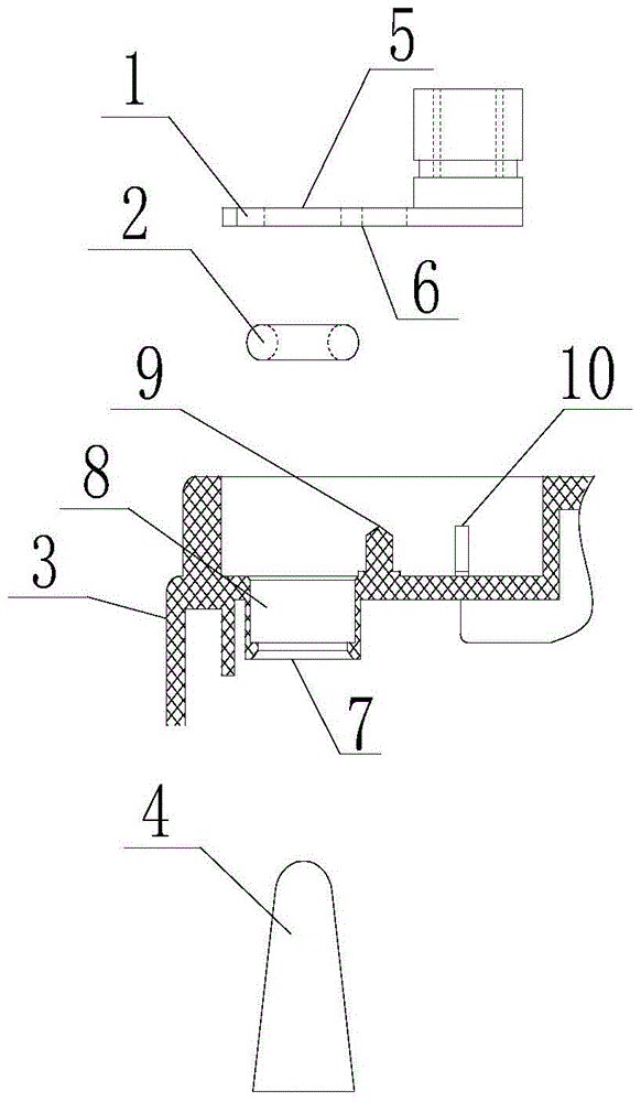
[0014] Such as figure 1 and figure 2 As shown, a novel colloid power battery terminal post sealing structure described in the present invention comprises a copper terminal 1, an O-shaped sealing ring 2, a pool cover terminal post connector 3 and a tapered lead pole post 4. The copper terminal 1 is a right-angled terminal, a welding hole 5 is provided at one end of the copper terminal 1, a fixing hole 6 is provided beside the welding hole 5, and a fixing hole 6 is provided on the terminal column connector 3 of the pool cover. A pool cover end column hole 7, an annular groove 8 is provided above the pool cover end column hole 7, a terminal fixing column 9 is provided beside the annular groove 8, and a terminal fixing column 9 is provided beside the terminal fixing column 9 Limiting card 10; the pool cover end column hole 7 is set on the conical lead po...


PUM


Abstract

The present invention relates to a new sealing structure for colloid power battery terminals, which consists of copper terminals, O-shaped sealing rings, pool cover terminal connectors and tapered lead poles. The copper terminals are right-angled terminals. A welding hole is provided at one end of the copper terminal, a fixing hole is provided beside the welding hole, a pool cover end post hole is provided on the pool cover end post connector, and above the pool cover end post hole An annular groove is provided, a terminal fixing column is arranged beside the annular groove, and a terminal limit card is arranged beside the terminal fixing column. The invention has good sealing performance, no leakage of acid solution, avoids thermal runaway caused by electrolyte leakage, reduces corrosion risk, reduces internal resistance, improves current carrying capacity and ensures high-current safety performance.

Description

technical field [0001] The invention relates to a sealing structure, in particular to a battery terminal post sealing structure. Background technique [0002] The current sealing structure of the terminal post of the gel battery is easily affected by a series of unstable factors such as the size deviation of the pole and the rubber ring, the surface roughness, and the deviation of the assembly operation, so that the fit cannot be completely sealed, and the poor sealing of the terminal post will cause acid leakage. , acid climbing phenomenon, and cause corrosion to the connection point and related components, affecting the normal use of the battery. After acid leakage, it must be cleaned up and pollute the environment. The current carrying capacity and high current safety cannot be guaranteed. Contents of the invention [0003] Purpose of the invention: The purpose of the present invention is to overcome the deficiencies in the prior art, provide a kind of good sealing perf...

Claims


Application Information

Patent Timeline
Patent Type & Authority Patents(China)
IPC IPC(8): H01M2/08H01M2/30H01M50/184H01M50/188H01M50/193H01M50/552
CPCH01M50/148H01M50/183H01M50/543Y02E60/10
Inventor 何治堂史仲华路建良张婷储浩芳许虎城
Owner 无锡华燕新电源有限公司
Why Eureka
Try Eureka