Method for designing large-power-resisting broadband radar antenna cover

A radar radome and design method technology, applied in the direction of the radiation unit cover, etc., can solve the problem of unsuitable large-scale ground radome

Active Publication Date: 2015-04-29
HARBIN TOPFRP COMPOSITE
View PDF3 Cites 10 Cited by
  • Summary
  • Abstract
  • Description
  • Claims
  • Application Information

AI Technical Summary

Problems solved by technology

[0004] The purpose of the present invention is to solve the problem that the current method of designing radome starting from material resear

Method used


Image

  • Method for designing large-power-resisting broadband radar antenna cover
  • Method for designing large-power-resisting broadband radar antenna cover
  • Method for designing large-power-resisting broadband radar antenna cover

Examples


specific Embodiment approach 1

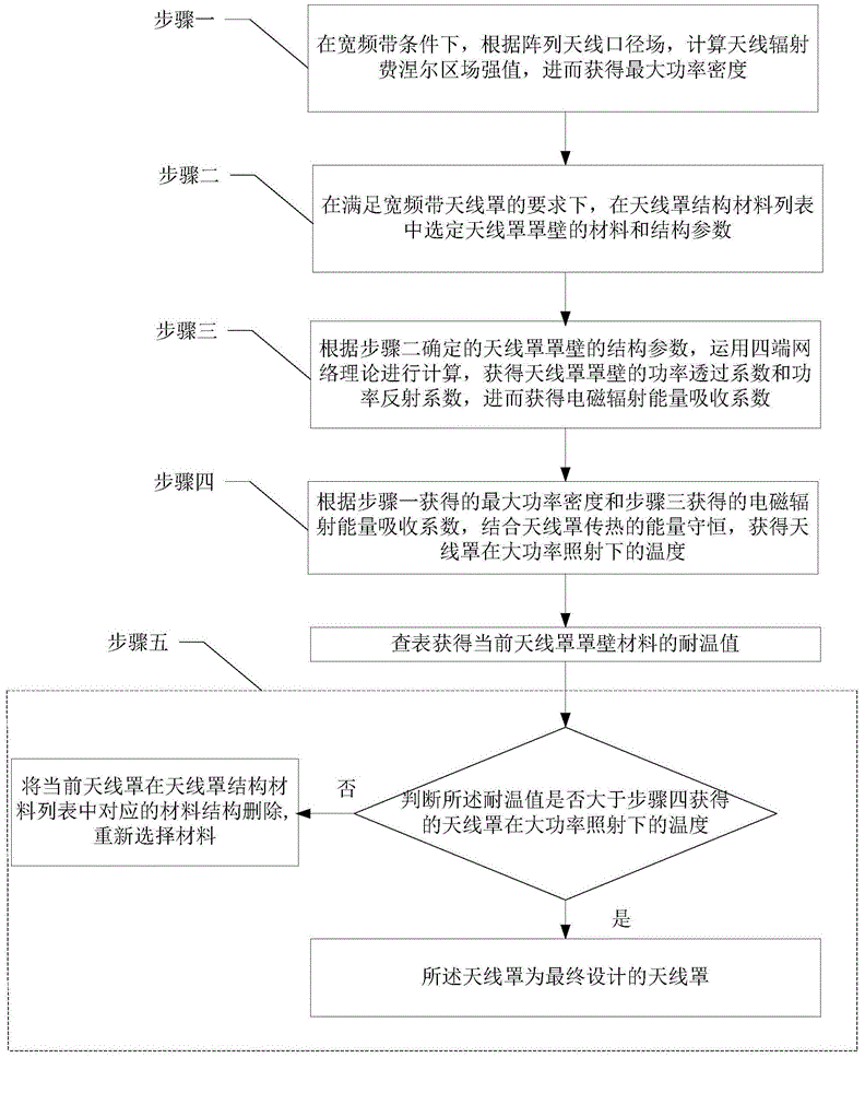
[0017] Specific implementation mode 1: Combination figure 1 To explain this embodiment, the design method of a high-power-resistant broadband radome described in this embodiment includes the following steps:

[0018] Step 1: Under broadband conditions, calculate the field strength E of the antenna radiation Fresnel zone according to the aperture field of the array antenna, and then obtain the maximum power density P of the antenna radiation m ;

[0019] Step 2: Under the requirement of wide-band radome, select the material and structural parameters of the radome cover in the list of radome structure materials;

[0020] Step 3: According to the structural parameters of the radome cover wall determined in step 2, use four-terminal network theory to calculate to obtain the power transmission coefficient and power reflection coefficient of the radome cover wall, and then obtain the electromagnetic radiation energy absorption coefficient L;

[0021] Step 4: According to the maximum power de...

specific Embodiment approach 2

[0024] Embodiment 2: This embodiment is a further limitation on the design method of a high-power-resistant broadband radome described in Embodiment 1.

[0025] In step 1, under the condition of wide frequency band, calculate the field strength value E of the antenna radiation Fresnel zone according to the aperture field of the array antenna, and then obtain the maximum power density P m The method is:

[0026] Take the center of the antenna port surface as the origin O, establish a rectangular coordinate system O-XYZ on the XY plane of the antenna port surface, and calculate the field strength value E of the antenna in the Fresnel zone according to the antenna port surface distribution g(x,y) P :

[0027] E P = j ( 1 + cos θ ) 2 λ e - jkr r ∫ ∫ ( s ) g ( ξ , η ) exp [ jk ( αξ + βη ) - ( ξ 2 + η 2 ) - ( αξ + βη ) 2 2 ] dξdη

[0028] In t...

specific Embodiment approach 3

[0037] Embodiment 3: This embodiment is a further limitation on the design method of a high-power-resistant broadband radome described in Embodiment 1 or 2,

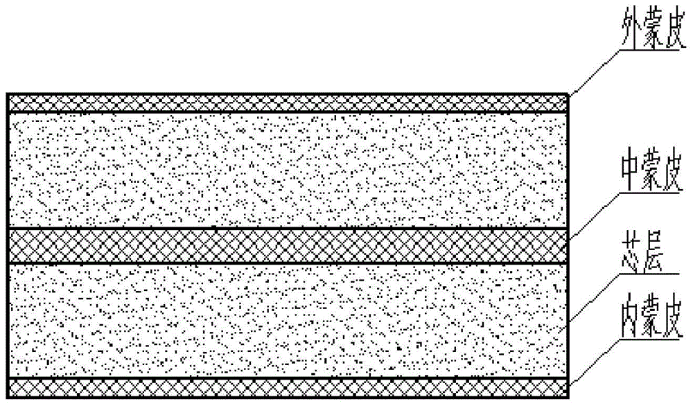
[0038] In step 2, the radome cover wall structure is a C sandwich cover wall structure, the C sandwich cover wall structure includes five layers of dielectric plates, and the five layers of dielectric plates are the first layer of skin and the third layer of skin. , The fifth layer of skin, the second layer of intermediate core layer and the fourth layer of intermediate core layer;

[0039] The materials of the first skin, the third skin and the fifth skin are all selected E glass fiber composite polyester resin FRP, and the materials of the second and fourth intermediate core layers are all polyurethane foam. The material properties of each layer are as follows:

[0040] Table C Material properties of each layer of the sandwich cover

[0041]

level one

Second floor

the third floor

Fourth floor

Fifth floor

Dielectric ...


PUM


Abstract

The invention discloses a method for designing a large-power-resisting broadband radar antenna cover, which belongs to the technical field of large-size ground radar antenna covers, and aims to solve the problems that a method for designing an antenna cover starting with material study is not applicable to large-size ground antenna covers. The method comprises the following steps: under the condition of broadband, acquiring maximum power density of radiation of an antenna according to an array antenna aperture field; selecting the material and structural parameters of the wall of the antenna cover; furthermore acquiring electromagnetic radiation energy absorption coefficients; furthermore, with the combination of energy conservation of heat conduction of the antenna cover, acquiring the temperature of the antenna cover under large-power radiation; judging whether the temperature resisting value of the material of the wall of the antenna cover at present is greater than the acquired temperature or not, if the temperature resisting value of the material of the wall of the antenna cover at present is greater than the acquired temperature, taking the antenna cover as a finally designed antenna cover, otherwise, reselecting an antenna cover structure material and redesigning the antenna cover. The method can be used for designing large-size ground radar antenna covers.

Description

Technical field [0001] The invention belongs to the technical field of large ground radar radomes. Background technique [0002] The large ground radome is a protective facility for the radar antenna, which can prevent the interference and influence of the environment on the radar equipment. The radome is mostly made of glass fiber reinforced plastic and foam structure composite materials. With the continuous development of electronic information technology, various large-scale warning, intelligence, and early warning radars have shown the characteristics of wider and wider working frequency bands and larger and larger transmission powers in the context of electronic countermeasures. Under the irradiation of high-power microwaves, the radome will generate high-frequency oscillations between the molecules of the composite material, causing local heating. When the temperature rises above the material temperature, the radome may be ablated or even burned. [0003] At present, the met...

Claims


Application Information

Patent Timeline
IPC IPC(8): H01Q1/42
Inventor 孟松孙宝华赵明刘禹宏
Owner HARBIN TOPFRP COMPOSITE
Why Eureka
Try Eureka