Multi-path permanent magnet synchronous motor control circuit based on FPGA chip

A permanent magnet synchronous motor and permanent magnet synchronous technology, which is applied in multiple motor speed/torque control, motor control, motor generator control, etc., to achieve the effect of cost saving and volume reduction

Inactive Publication Date: 2015-04-29
BEIJING RES INST OF PRECISE MECHATRONICS CONTROLS +1
View PDF4 Cites 3 Cited by
  • Summary
  • Abstract
  • Description
  • Claims
  • Application Information

AI Technical Summary

Problems solved by technology

However, traditional permanent magnet synchronous motor drives or inverters cannot meet this requirement

Method used


Image

  • Multi-path permanent magnet synchronous motor control circuit based on FPGA chip
  • Multi-path permanent magnet synchronous motor control circuit based on FPGA chip

Examples


Embodiment Construction

[0012] The present invention will be described in further detail below in conjunction with the accompanying drawings and embodiments.

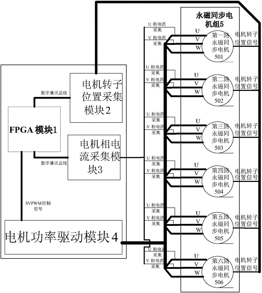
[0013] as attached figure 1 As shown, an FPGA chip-based multi-channel permanent magnet synchronous motor control circuit provided by the present invention includes an FPGA module 1 , a motor rotor position acquisition module 2 , a motor phase current acquisition module 3 and a motor power drive module 4 . The phase current signal input end of the FPGA module 1 is connected with the signal output end of the motor phase current acquisition module 3 through the digital communication bus, and the rotor position signal input end of the FPGA module 1 is connected with the signal output end of the motor rotor position acquisition module 2 through the digital communication bus connected. The rotor position signal acquisition end of the motor rotor position acquisition module 2 communicates with the rotor position signal output end of the permanent m...


PUM


Abstract

The invention belongs to a motor control circuit, and particularly discloses a multi-path permanent magnet synchronous motor control circuit based on an FPGA chip. The multi-path permanent magnet synchronous motor control circuit comprises an FPGA module, wherein the phase current signal input end of the FPGA module is communicated with the signal output end of a motor phase current acquisition module; the rotor position signal input end of the FPGA module is communicated with the signal output end of a motor rotor position acquisition module; the rotor position signal acquisition end of the motor rotor position acquisition module is communicated with the rotor position signal output end of a permanent magnet synchronous motor unit; the signal input end of the motor phase current acquisition module is communicated with the phase current signal output end of the permanent magnet synchronous motor unit; the signal input end of a motor power driving module is communicated with the SVPWM control signal output end of the FPGA module; the signal output end of the motor power driving module is communicated with current signal input end of the permanent magnet synchronous motor unit. The multi-path permanent magnet synchronous motor control circuit can realize driving control and cooperative control functions of a multi-path permanent magnet synchronous motor.

Description

technical field [0001] The invention belongs to a motor control circuit, in particular to a multi-channel permanent magnet synchronous motor control circuit. Background technique [0002] In the current motor control system, generally a motor driver or an inverter is used to drive a permanent magnet synchronous motor to realize motor operation. The core chip inside this kind of motor driver or inverter is usually a DSP chip or MCU chip dedicated to motor control. As we all know, due to the complexity of the permanent magnet synchronous motor control algorithm, ordinary motor control DSP chips or MCU chips can only control one or at most two permanent magnet synchronous motor movements, and the control frequency of the internal motor control current loop algorithm is only Around 100KHz. Therefore, the core control chip (DSP or MCU chip) inside the motor driver or inverter limits the number and speed of its control of permanent magnet synchronous motors in terms of control. ...

Claims


Application Information

Patent Timeline
Patent Type & Authority Applications(China)
IPC IPC(8): H02P6/04H02P21/00
CPCH02P6/04H02P2207/05
Inventor 卢二宝魏思维于志远黄玉平丁伟涛任丽平
Owner BEIJING RES INST OF PRECISE MECHATRONICS CONTROLS
Why Eureka
Try Eureka