Multi-source imaging load for unmanned aerial vehicle

A technology for unmanned aerial vehicles and payloads, applied in image communication, television, standard conversion, etc., can solve the problems of large circuit design size, repetitive design, load out of control, etc., to reduce development time, improve integration, and powerful functions Effect

Active Publication Date: 2015-04-29
BEIJING INST OF AEROSPACE CONTROL DEVICES
View PDF6 Cites 15 Cited by
  • Summary
  • Abstract
  • Description
  • Claims
  • Application Information

AI Technical Summary

Problems solved by technology

[0003] Due to the complex hardware interface and data format standards of imaging equipment, UAV payloads often need to design different interfaces and switching circuits for different imaging equipment, resulting in increased payload volume and increased energy consumption; in order to ensure the video data path of multi-source imaging payloads Choice, the real-time video switching method needs to implement redundant data links internally to transmit multiple video data at the same time, resulting in a large circuit design size, while the non-real-time video switching method needs to be hot-started when the load is powered on, resulting in the load The air is out of control; in order to enrich the function design of the photoelectric load, it is usually chosen to add a new module to the load for each new function, resulting in high design costs; the external interface design of the traditional load is relatively single, and the data format is not uniform. It is difficult to change after being finalized, and it is even more difficult to adapt to changing external interface requirements, resulting in the need for repeated development of each new interface, resulting in a lot of repeated design and labor
Such problems lead to high overall cost of drones, which greatly limits the promotion and use of drones in many fields

Method used


Image

  • Multi-source imaging load for unmanned aerial vehicle
  • Multi-source imaging load for unmanned aerial vehicle
  • Multi-source imaging load for unmanned aerial vehicle

Examples


Embodiment Construction

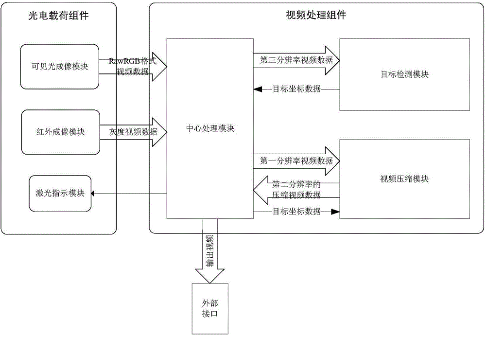
[0026] Such as figure 1 As shown, the UAV multi-source imaging load of the present invention includes a photoelectric load assembly and a video processing assembly, and the photoelectric load assembly includes a visible light imaging module, an infrared imaging module and a laser pointer module; the video processing assembly includes a central processing module, Target detection module and video compression module;

[0027] The visible light imaging module outputs the first-resolution RawRGB format video data to the central processing module, the infrared imaging module outputs the grayscale video data to the central processing module and is converted into the first-resolution RawRGB format video data by the central processing module, and the laser pointer module It is connected with the central processing module and its switch is controlled by the central processing module;

[0028] The central processing module sends the RawRGB format video data of the first resolution to t...


PUM


Abstract

The invention discloses a multi-source imaging load for an unmanned aerial vehicle. The multi-source imaging load comprises a visible light imaging module, an infrared imaging module, a laser indication module, a central processing module, a target detection module and a video compression module, wherein the central processing module directly controls the laser indication module, acquires video data from the visible light imaging module and the infrared imaging module, sends the video data with the native resolution to the video compression module after converting the video data into data in the same data format, sends down-sampled video data to the target detection module, and outputs compressed video data returned by the video compression module and target coordinate data returned by the target detection module to an external interface. The load has the advantages of small size, low weight, strong function and the like and can fully meet requirements of day-and-night photoelectric detection at middle and close distances, and convenience can be brought to usage under different environment and application conditions through matched usage of multiple loads.

Description

technical field [0001] The invention relates to a multi-source imaging payload for an unmanned aerial vehicle. Background technique [0002] UAVs are more and more widely used in film and television, search and rescue, police, military and other fields. Small UAVs are popular with users for their low cost, simple use and powerful functions. As the key equipment of the UAV, the photoelectric imaging load undertakes the work of the UAV's ground reconnaissance, target search, tracking, positioning, etc., and is one of the core loads of the UAV. With the development of technology, the production and development of UAVs have gradually realized modularization, processization and batching, but there is no unified standard for the design of UAV payloads. As the key components of UAV payload, the optical imaging payload and image processing module is the module with the most difficult design, the highest cost and the most complex functions in UAV payload design. [0003] Due to the...

Claims


Application Information

Patent Timeline
Patent Type & Authority Applications(China)
IPC IPC(8): H04N5/225H04N5/14H04N7/01
Inventor 刘少鹏景彦哲耿欣
Owner BEIJING INST OF AEROSPACE CONTROL DEVICES
Why Eureka
Try Eureka