
Dual-purpose numerical control processing machine tool for outer circle and spiral slot of rice-milling sand roller

A technology for CNC machining of machine tools and spiral grooves, which is applied in metal processing mechanical parts, metal processing equipment, tools for lathes, etc., can solve the problems of large machining errors, waste of manpower, poor machining accuracy, etc., and achieves the requirements of improving machining accuracy. , The effect of improving production efficiency and quality

Active Publication Date: 2015-05-06
湖北省鄂州市天元砂辊有限责任公司
View PDF8 Cites 1 Cited by
  • Summary
  • Abstract
  • Description
  • Claims
  • Application Information

AI Technical Summary

Problems solved by technology

[0004] The above existing patented technologies all process the outer circle and the spiral groove independently, and process them on different equipment, and are all controlled manually, and have the following defects: First, because two separate processes are involved, Therefore, two devices are needed, which take up more space. Each device must be controlled by at least one person, and two devices require at least two workers, which wastes a lot of manpower. Moreover, both devices require manual handling of workpieces during work. There are also many, the labor intensity of the workers is high, the labor is greatly wasted, the production cost is high, and the processing efficiency is low
Second, the processing quality of the product is not easy to guarantee, because two processes, two equipment and personnel are used for processing, and the positioning and clamping of the secondary workpiece are used before and after. The benchmark has moved and changed, and the size and accuracy after processing are not easy. Guarantee; and because most of the rice milling emery rollers are composed of two or more sections, some of which have a diameter of more than 400mm, more than 10 sections, and a total length of more than 1000mm, the existing equipment generally uses a knife bowl tool when processing the outer circle , processed on the outer machine tool in a single section, so the same group of emery rollers cannot be avoided. The size of each section after processing is not consistent, but the emery rollers assembled in the rice machine are connected together by a shaft, and if the dimensions are inconsistent, it will be There are different degrees of inverted ridges, and when processing the spiral groove in the next process, it is difficult to ensure that the groove shape size, groove width, and groove depth are uniform. In addition, the diameter of the existing knife bowl is about 100mm, which is made of carbon steel. The pressed flake bowl shape is heavy in brittleness and extremely poor in wear resistance. One knife bowl can only process 1 to 2 sets of emery rollers. It is constantly worn during processing, and the size of the knife bowl keeps getting smaller. The surface size of the processed emery roller is very irregular, and the processing accuracy is very poor
Thirdly, the existing rice milling emery roller processing machine tools are generally manually operated and manually controlled, and the processing error is relatively large. It is difficult to meet the ideal size and accuracy requirements, which seriously affects the performance of the rice machine and the processing quality of rice.

Method used


Image

  • Dual-purpose numerical control processing machine tool for outer circle and spiral slot of rice-milling sand roller
  • Dual-purpose numerical control processing machine tool for outer circle and spiral slot of rice-milling sand roller
  • Dual-purpose numerical control processing machine tool for outer circle and spiral slot of rice-milling sand roller

Examples


Embodiment Construction

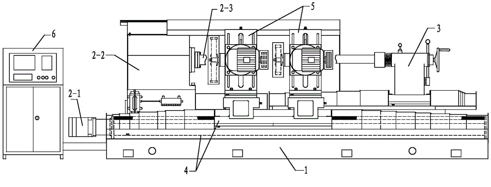
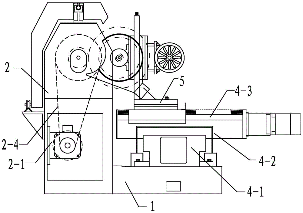
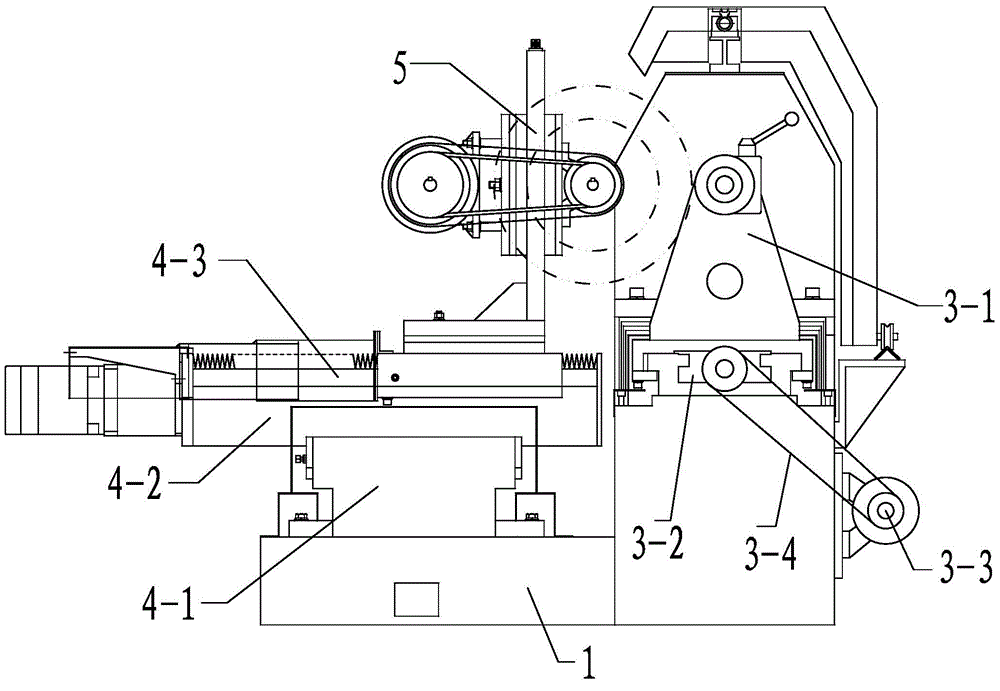
[0037] The present invention will be further described below in conjunction with the accompanying drawings. like Figure 1 to Figure 4 A dual-purpose CNC machining machine tool for the outer circle and spiral groove of the rice milling emery roller shown, including a machine base 1, a spindle box part 2 arranged on the machine base, a tailstock part 3, a tool rest part 5 and a feed part 4 , it is characterized in that: the spindle box part 2 includes a spindle servo motor 2-1, a spindle housing 2-2, a spindle 2-3 and a transmission mechanism 2-4 connecting the spindle servo motor and the spindle, wherein the transmission mechanism 2-4 Including the main shaft reducer 2-5 and the synchronous toothed belt 2-6, the main shaft servo motor 2-1 is connected to the main shaft through the main shaft reducer 2-5 and the synchronous toothed belt 2-6, and the main shaft servo motor 2-1 The speed of the main shaft can be adjusted by stepless speed change, and the appropriate speed can be...


PUM

PropertyMeasurementUnit
Lengthaaaaaaaaaa

Abstract

The invention provides a dual-purpose numerical control processing machine tool for an outer circle and a spiral slot of a rice-milling sand roller. The processing machine tool comprises a machine base, a spindle box part, a tail base part, a knife rest part and a feeding part. The dual-purpose numerical control processing machine tool is characterized in that the spindle box part comprises a spindle servo motor, a spindle box body, a spindle and a transmission mechanism, wherein the knife rest part consists of a sand-roller outer circle processing knife rest and a sand roller spiral slot processing knife rest; the feeding part consists of a transverse feeding rail, a slide table and two longitudinal feeding rails, the transverse feeding rail is transversely arranged on the machine base, the slide table is in sliding connection with the transverse feeding rail, the two longitudinal feeding rails are arranged on the slide table in parallel, and are perpendicular to the transverse feeding rail; the sand roller outer circle processing knife rest and the sand roller spiral slot processing knife rest are arranged on the two longitudinal feeding rails respectively. According to the dual-purpose numerical control processing machine tool, the product quality is improved, the sand roller processing precision requirements are improved, and the quality of rice processed by the rice-milling sand roller is further improved.

Description

technical field [0001] The patent of the invention relates to the field of new machinery in traditional industries, in particular to a machine tool for dual-purpose CNC machining of the outer circle and spiral groove of rice milling emery rollers. Background technique [0002] Rice milling emery roller is a core component of grain machinery and rice processing equipment. Its manufacturing process is relatively complicated, with many procedures and high technical difficulty. During the production process, the dimensions of the rice milling emery roller must be processed by a special machine tool for rice milling emery roller to meet the requirements of its own design drawings. The processing procedure of rice milling emery roller is roughly divided into outer circle processing, end surface processing, spiral groove processing and drilling processing. The outer circle processing of rice milling emery roller must ensure the requirements of outer circle size, cylindricity, strai...

Claims


Application Information

Patent Timeline
IPC IPC(8): B23Q5/10B23Q5/40B23B21/00B23B23/00
CPCB23B23/00B23B27/083B23Q1/25B23Q5/10B23Q5/402
Inventor 卢波郑良
Owner 湖北省鄂州市天元砂辊有限责任公司
Learn More