Cutting fluid circulating device

A technology of circulating device and cutting fluid, applied in maintenance and safety accessories, solid separation, magnetic separation, etc., can solve problems such as pipeline blockage, increased maintenance cost of cutting fluid, and reduced filtration performance of cutting fluid circulating device.

Active Publication Date: 2015-05-06
湖北润达新材料有限公司
View PDF7 Cites 8 Cited by
  • Summary
  • Abstract
  • Description
  • Claims
  • Application Information

AI Technical Summary

Problems solved by technology

The existing cutting fluid circulation device is generally composed of a box body, a water supply system, a circulation system, and a filtration system. Most of the filtration systems use filter paper to filter, and grinding iron chips and filter paper are easy to adhere together, which leads to poor performance of the cutting fluid. Greatly reduced, such as the blockage of the pipeline in the cutting fluid circulation device, the reduction of the filtration performance in the cutting fluid circulation device, the increase in the maintenance cost of the cutting fluid, etc.

Method used


Image

  • Cutting fluid circulating device
  • Cutting fluid circulating device
  • Cutting fluid circulating device

Examples


Embodiment Construction

[0021] The present invention will be further described below in conjunction with the accompanying drawings and specific embodiments.

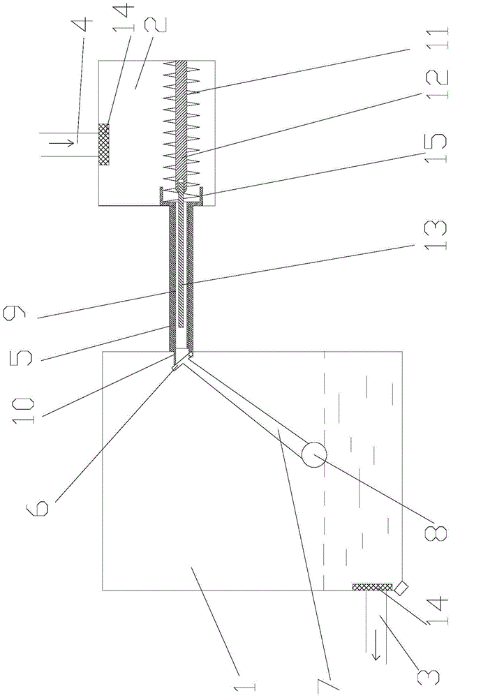
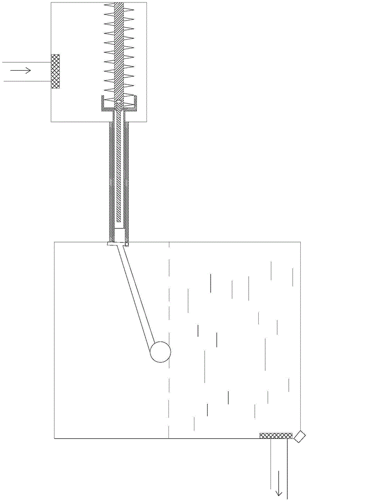
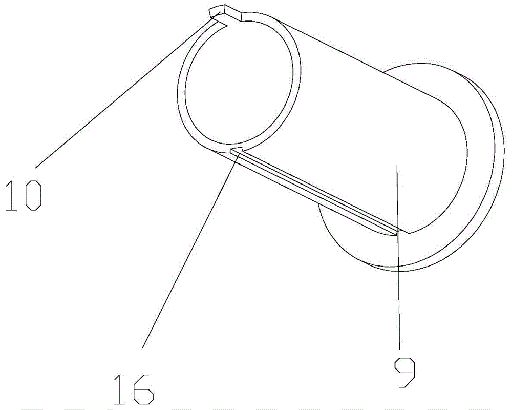
[0022] As shown in the figure, the cutting fluid circulation device of the present invention includes a first box 1 and a second box 2, the first box 1 is provided with an outlet channel 3, and the second box 2 is provided with an inlet channel 4, The first box body 1 communicates with the second box body 2 through the connecting pipe 5, and the distance from the bottom surface of the second box body 2 to the ground is larger than the distance from the bottom surface of the first box body 1 to the ground; the connecting pipe 5 and the first box body The body 1 is connected to one end hinged with a baffle 6, and the baffle 6 is connected to a floating ball 8 through a rocker 7; the inner wall of the connecting pipe 5 is slidingly fitted with a sliding tube 9, and one end of the sliding tube 9 is provided with an extending end 10, and the other en...


PUM


Abstract

The invention discloses a cutting fluid circulating device which comprises a first box body (1) and a second box body (2), wherein the first box body (1) is connected to the second box body (2) through a connecting pipe (5); one end, connected to the first box body (1), of the connecting pipe (5) is articulated with a baffle plate (6); the baffle plate (6) is connected with a floating ball (8) through a rocking bar (7); the inner wall of the connecting pipe (5) is matched with a slip pipe (9) in a sliding manner; one end of the slip pipe (9) is provided with an extension end (10); the other end of the slip pipe (9) is connected with the second box body (2) through an on-off device; the on-off device comprises a pressure spring (11) and a core rod (12); one end of the core rod (12) is fixedly arranged on the inner wall of the second box body (2); the pressure spring (11) sleeves on the core rod (12); one end of the pressure spring (11) is connected with the inner wall of the second box body (2), and the other end of the pressure spring (11) is connected with the end face of the slip pipe (9); the core rod (12) is provided with a magnet (13). According to the cutting fluid circulating device, the cutting fluid circulating service efficiency is high.

Description

technical field [0001] The invention relates to a cutting fluid circulation device, in particular to a cutting fluid circulation device in the recycling of cutting fluid in machine tool processing. Background technique [0002] Cutting fluid is an industrial liquid used in the metal cutting process to cool and lubricate tools and workpieces. The cutting fluid is made of a variety of super functional additives through scientific compounding. It also has good cooling performance, Lubricating performance, anti-rust performance, degreasing and cleaning function, anti-corrosion function, easy to dilute and other characteristics. At present, the cutting fluid used in various machine tools is recycled, so as to reduce the cost of cutting fluid. The existing cutting fluid circulation device is generally composed of a box body, a water supply system, a circulation system, and a filtration system. Most of the filtration systems use filter paper to filter, and grinding iron chips and ...

Claims


Application Information

Patent Timeline
Patent Type & Authority Applications(China)
IPC IPC(8): B23Q11/10
CPCB03C1/30B23Q11/10B23Q11/1069
Inventor 不公告发明人
Owner 湖北润达新材料有限公司
Why Eureka
Try Eureka