
Device for grinding lead screw precisely

A lead screw and precision grinding technology, which is applied in the direction of tangent devices, machine tools designed for grinding the rotating surface of workpieces, grinding machines, etc., can solve the problems of decreased grinding accuracy, affecting grinding effect, and high manufacturing cost, and achieve reduced surface roughness, Improved fatigue strength and service life, low cost effect

Inactive Publication Date: 2015-05-06
UNIV OF SCI & TECH LIAONING
View PDF5 Cites 22 Cited by
  • Summary
  • Abstract
  • Description
  • Claims
  • Application Information

AI Technical Summary

Problems solved by technology

Most of the traditional fine-grinding lead screw grinders use fixed grinding heads, and the grinding heads are all made of grinding wheels. The machining allowance of the precision lead screw is about 10 μm. During processing, the grinding wheel and the grinding head are in direct contact with the lead screw. This processing method requires The positioning accuracy of the grinding head and the screw to be ground is very high, and after the grinding head is worn out, it will directly affect the grinding effect, resulting in a decrease in grinding accuracy
In order to ensure the reliability of screw grinding, the structure of this type of machine tool is relatively complicated, requiring professional operation, and the manufacturing cost is high

Method used


Image

  • Device for grinding lead screw precisely
  • Device for grinding lead screw precisely
  • Device for grinding lead screw precisely

Examples


Embodiment Construction

[0014] The present invention will be further described below in conjunction with the accompanying drawings.

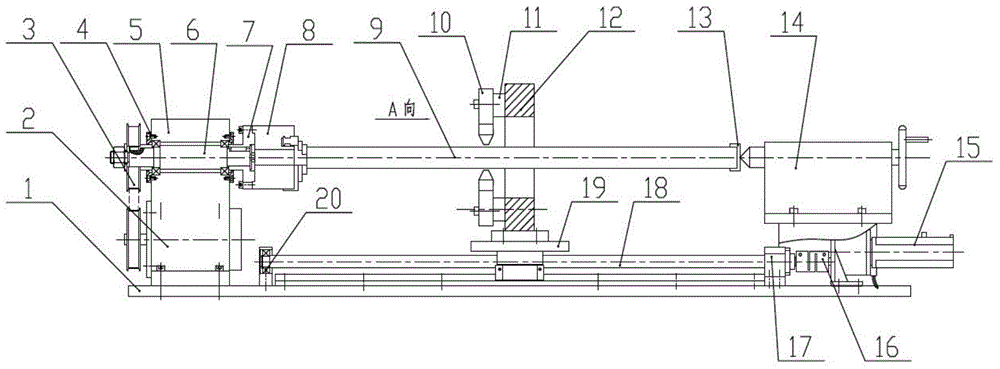
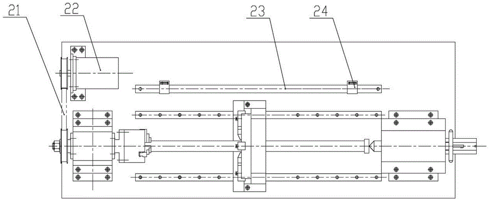
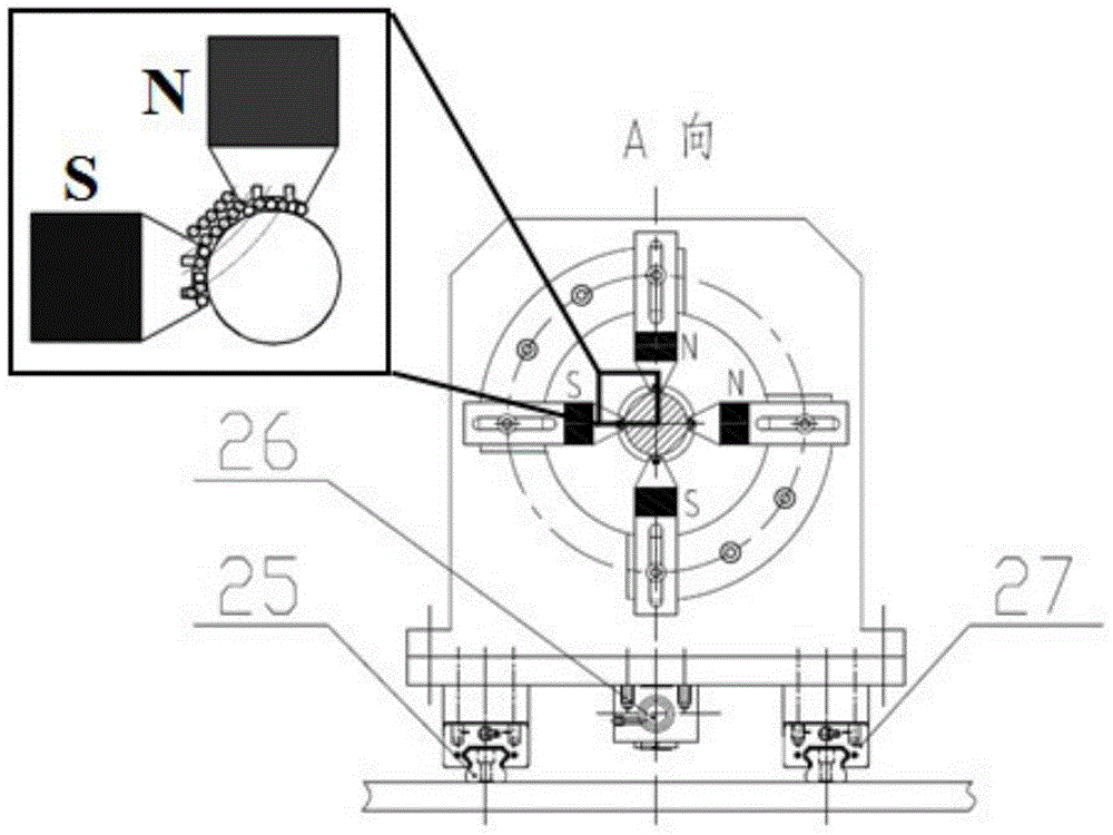
[0015] Such as figure 1 , figure 2 with image 3 As shown, a device for precision grinding screw, the device consists of a base plate 1, a pad 2, a synchronous pulley 3, a main shaft end cover 4, a main shaft positioning seat 5, a main shaft 6, a flange 7, a three-jaw automatic Centering chuck 8, workpiece 9, grinding magnetic pole group 10, arc iron 11, magnetic pole support seat 12, workpiece support 13, tailstock 14, auxiliary servo motor 15, coupling 16, screw positioning bearing seat 17 , lead screw 18, supporting plate 19, lead screw positioning bearing seat 220, synchronous belt 21, reduction motor 22 for main servo, sensor positioning seat 23, limit sensor 24, two slideways 25, lead screw nut 26 and sliding block 27, the main servo reducer 22 and the auxiliary servo motor 15 are fixed on the base plate 1 with recessed bolts, the limit sensor 24 is installed...


PUM


Abstract

The invention discloses a device for grinding a lead screw precisely, which can improve the precision grinding quality and efficiency of the lead screw. The device comprises a base plate, a cushion block, a synchronous pulley, a spindle end cover, a spindle positioning seat, a spindle, a flange plate, a three-jaw self-centering chuck, a grinding magnetic pole group, a curved iron, a magnetic pole supporting seat, a workpiece support, a tailstock, an auxiliary servo motor, a shaft coupler, a first lead screw positioning bearing block, the lead screw, a supporting plate, a second lead screw positioning bearing block, a synchronous belt, a main servo deceleration motor, a sensor positioning seat, a limit sensor, two slideways, a lead screw nut and a sliding block. According to the device disclosed by the invention, the specifications of the magnetic poles in the grinding magnetic pole group can be replaced upon the type of the lead screw, the operation is simple and the cost is low. The device is flexibly contacted with the workpiece by a magnetic abrasive brush, so the surface of the workpiece cannot be scratched and damaged during precision grinding; after the surface of the lead screw is ground and polished, the surface roughness can be reduced and the smoothness can be increased; besides that, with the residual compressive stress on the surface, the fatigue strength and the service life of the surface can be improved.

Description

technical field [0001] The invention relates to a device for grinding and finely grinding a workpiece by using magnetic force, in particular to a device for finely grinding a lead screw. Background technique [0002] In the field of machinery manufacturing, machine tools used to process various parts, such as lathes, milling machines, planers, grinding machines, drilling machines and large machining centers, etc., mostly rely on precision screw as the transmission element, and its main function is to convert rotary motion into linear motion. motion, or convert torque into axial force. Precision lead screws are also widely used in aerospace, nuclear industry, medical and other industries. Generally speaking, these occasions generally have higher requirements on the accuracy, fatigue strength and reliability of lead screws. Most of the traditional fine-grinding lead screw grinders use fixed grinding heads, and the grinding heads are all made of grinding wheels. The machining ...

Claims


Application Information

Patent Timeline
IPC IPC(8): B24B1/00B24B5/04
CPCB23G9/00B23G2210/08
Inventor 焦安源全洪军李宗泽陈燕韩冰
Owner UNIV OF SCI & TECH LIAONING
Learn More