Combination automatic control method with single-joint manipulator under mixed suspension microgravity environments
What is AI technical title?
AI technical title is built by Patsnap AI team. It summarizes the technical point description of the patent document.
A technology of autonomous control and combination, applied in adaptive control, manipulator, general control system, etc., can solve the problems of ignoring the approximation error of neural network and not considering the influence, etc.
Inactive Publication Date: 2015-05-06
NORTHWESTERN POLYTECHNICAL UNIV
View PDF3 Cites 33 Cited by
Summary
Abstract
Description
Claims
Application Information
AI Technical Summary
This helps you quickly interpret patents by identifying the three key elements:
Problems solved by technology
Method used
Benefits of technology
Problems solved by technology
However, this method does not consider the influence of propeller thrust saturation on the performance of the controller, and ignores the approximation error of the neural network
Method used
Image
Click on the blue label to locate the original text in one second.
Reading with bidirectional positioning of images and text.
Examples
example 1
[0123] In the following examples, the control effects obtained by using the control method described in the present invention are as follows. In Example 1, the position and posture of the subject remains unchanged, and the joints are controlled to rotate.
[0124] n 0 = η d =[0 0 0 0 0 0] T m, rad
[0125] q 0 = 0 rad q d = π 2 rad
[0126] The propeller thrust saturation value is set to 30N, and the joint torque saturation value is set to 30Nm.
[0127] Among them, η 0 and η d are the initial position and posture and the desired position and posture of the subject, respectively. q 0 and q d are the initial and expected values of joint rotation angles of the assembly, respectively.
[0128] The control law parameters are set as follows:
[0129] Λ=0.5diag{0.5 0.5 0.5 0.5 0.5 0.5 0.5}
[0130] K D =50diag{1 1 1 1 1 1 0.5}
[0131] K S =50diag{1 1 1 1 1 1 0.5} ...
example 2
[0138] Example 2: Keep the joint position unchanged and control the body movement.
[0139] n 0 =[0 0 0 0 0 0] T m, rad
[0140] n d =[1 1 1 0 0 0] T m, rad
[0141] q 0 =q d = 0 rad
[0142] The propeller thrust saturation value is set to 30N, and the joint torque saturation value is set to 30Nm.
[0143] Among them, η 0 and η d are the initial position and posture and the desired position and posture of the subject, respectively. q 0 and q d are the initial and expected values of joint rotation angles of the assembly, respectively.
[0144] The control law parameters are set as follows:
[0145] Λ=0.5diag{0.5 0.5 0.5 0.5 0.5 0.5 0.3}
[0146] K D =50diag{1 1 1 1 1 1 0.3}
[0147] K S =50diag{1 1 1 1 1 1 0.3}
[0148] K P =50diag{1 1 1 1 1 1 0.3}
[0149] Γ ω =0.1Iσ w =30c w ∈[-4 4]Number of network nodes=401
[0150] Γ u =0.1Iσ u =1000c u ∈[-400 400]Number of network nodes=201
[0151] The position of the joints of the assembly remains unchan...
PUM
Abstract
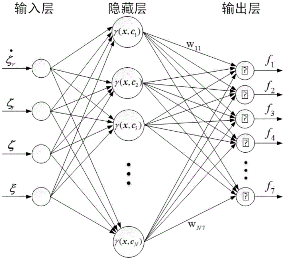
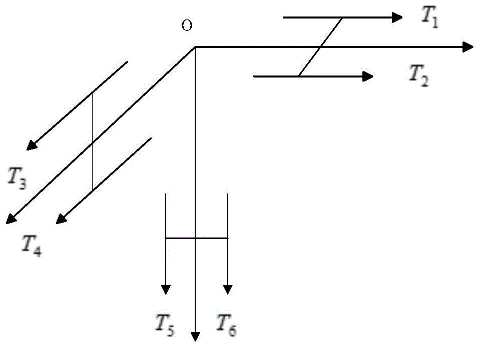
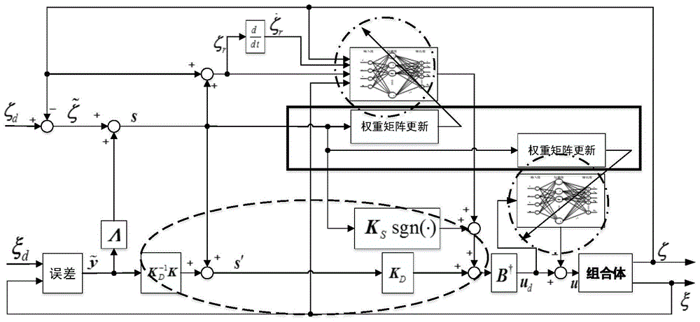
The invention provides a combination automatic control method with a single-joint manipulator under mixed suspension microgravity environments. The combination automatic control method comprises the following steps of 1, enabling a combination to be equivalent to an underwaterrobot, and establishing a kinematics equation and a dynamics equation; 2, approximating the dynamics equation of the combination by a radial basis function neural network, so as to obtain control force and control torque corresponding to the radial basis function neural network; 3, using a sliding mode control method, so as to obtain control force and control torque corresponding to sliding model control; 4, synthesizing the control force and control torque corresponding to the neural network and the control force and control torque obtained by the sliding model control method, and distributing thrust, so as to obtain a general vector which consists of thrust and joint torque of each propeller; approximating the thrust deviation of the corresponding thruster through the radial basis function neural network, so as to obtain the estimation value of the thrust deviation; 5, combining the results obtained in step 2, step 3 and step 4, obtaining the general vector consisting of the thrust and the joint torque of the corresponding propeller, and further obtaining the thrust and the joint torque of the corresponding propeller, so as to realize the automatic control.
Description
technical field [0001] The invention relates to the motion control technology of an underwaterrobot, in particular to an autonomous control method for an assembly with a single-joint mechanical arm in a mixed suspension microgravity environment. Background technique [0002] The assembly is formed by docking the experimental body and the floating target, and contains a joint that can be controlled to rotate. Since the working environment of the assembly is in water, it can be regarded as an underwaterrobotsystem with a single-joint manipulator. The underwater robotsystem has the characteristics of nonlinearity, time-varying, strong coupling, etc., which poses a great challenge to the design of its controller. [0003] At present, a lot of research has been carried out on the control technology of underwater vehicles. Various control methods including linear control, robust control, fuzzy control, adaptive control, etc. have been used for motion control of underwater veh...
Claims
Application Information
Patent Timeline
Application Date:The date an application was filed.
Publication Date:The date a patent or application was officially published.
First Publication Date:The earliest publication date of a patent with the same application number.
Issue Date:Publication date of the patent grant document.
PCT Entry Date:The Entry date of PCT National Phase.
Estimated Expiry Date:The statutory expiry date of a patent right according to the Patent Law, and it is the longest term of protection that the patent right can achieve without the termination of the patent right due to other reasons(Term extension factor has been taken into account ).
Invalid Date:Actual expiry date is based on effective date or publication date of legal transaction data of invalid patent.

