Composite bridge deck applied to long-span bridges and city bridges

A combined bridge and long-span technology, applied in the direction of bridges, bridge parts, bridge materials, etc., can solve the problems of pure steel bridge deck structure corrosion, heavy concrete slab weight, poor torsion resistance, etc., and reduce deformation asynchronous. , Small amount of welding, the effect of reducing stress

Active Publication Date: 2015-05-06
HENAN PROVINCIAL COMM PLANNING & DESIGN INST CO LTD
View PDF5 Cites 14 Cited by
  • Summary
  • Abstract
  • Description
  • Claims
  • Application Information

AI Technical Summary

Problems solved by technology

In addition, due to the harsh natural environment and loading environment of the bridge deck pavement, it is subjected to multiple effects such as heavy loads, high temperatures, and vibrations, resulting in corrosion of the pure steel bridge deck structure, fatigue cracks in the welds, and widespread pavement layers. Cracking and other diseases, in severe cases, the bridge deck system needs to be demolished and rebuilt
[0003] The composite girder composed of steel girder and concrete slab avoids the problems of pure steel bridge deck to a certain extent, but most of the steel girders of the composite girder adopt the form of open section, and the steel girders need to rely on horizontal connections to form a whole; steel girders It is not synchronized with the deformation of the concrete slab under the action of temperature force and shrinkage force; the top of the steel beam needs to be in full contact with the concrete slab, which has the problems of poor torsion resistance, heavy weight of the concrete slab, and large amount of on-site welding, so its application range is limited. limit

Method used


Image

  • Composite bridge deck applied to long-span bridges and city bridges

Examples


Embodiment Construction

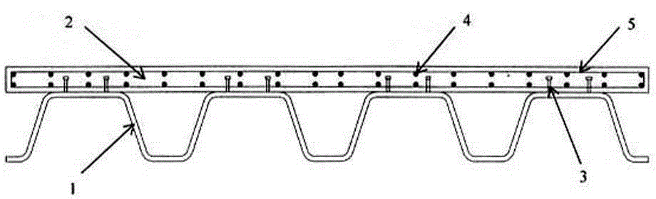
[0021] Such as figure 1 As shown, the composite bridge deck applied to long-span bridges and urban bridges according to the present invention includes a bridge deck body composed of a lower corrugated steel plate 1 (bottom plate) and an upper concrete plate 2 (top plate): The shear connector 3 symmetrically welded on the crest of the corrugated steel plate 1 extends upwards into the concrete slab 2; in the middle of the concrete slab 2, a reinforcing steel bar 4 is evenly arranged along the length of the bridge, and the circular stirrup 5 of the reinforcing steel bar is bundled After being connected to form a whole; the annular stirrup 5 and the shear connector 3 are connected to each other to ensure sufficient shear rigidity between the corrugated steel plate 1 and the concrete slab 2 .

[0022] In actual use, the shear connector 3 can be a stud, section steel or perforated plate structure; according to the section structure and the force analysis of the bridge deck, the thic...


PUM

PropertyMeasurementUnit
thicknessaaaaaaaaaa
thicknessaaaaaaaaaa
diameteraaaaaaaaaa

Abstract

The invention discloses a composite bridge deck applied to long-span bridges and city bridges. The composite bridge deck comprises a bridge deck body, wherein the bridge deck body is formed through combining a lower wave-shaped steel plate and an upper concrete slab; shear connectors which are symmetrically welded to wave crests of the wave-shaped steel plate upwards extend into the concrete slab; reinforcing steel bars and annular hoop reinforcements which are used for bundling up the reinforcing steel bars are arranged at the middle part of the concrete slab in a balanced manner. According to the composite bridge deck, the characteristics of the wave-shaped steel plate and the characteristics of the concrete slab are combined together, properties of materials are fully utilized, the flexural bearing capacity is enough under heavy loads, the deformation is small enough under the action of concentrated loads, and too-large secondary stress resulting from weld seams can be avoided; a top plate of a steel bridge deck is replaced with the concrete slab, so that the construction cost of a bridge floor system can be reduced; the quantity of welding is very small, so that the damage to the bridge deck caused by defects of a welding process can be reduced; due to the wrinkling effect of the wave-shaped steel plate, the problem that the deformation of the steel plate and the deformation of concrete are non-synchronous can be greatly solved, and the cracking of the transverse bridge direction of the bridge deck is avoided.

Description

technical field [0001] The invention relates to bridge engineering, in particular to a composite bridge deck applied to long-span bridges and urban bridges. Background technique [0002] Orthotropic steel bridge decks have the advantages of light weight, convenient transportation and erection, short construction period, and large bearing capacity. They are widely used in long-span bridges and urban bridges, but the amount of steel used in orthotropic steel bridge decks is large , The cost is high, the local deformation is large under the action of concentrated load, and secondary stress will be generated at the weld constraint; within the design life of the bridge, fatigue cracks are likely to occur due to repeated rolling by wheels. Due to the complex structure of the pure steel bridge deck, the large number of welds and the difficulty in welding, the requirements for factory manufacturing, on-site assembly accuracy and welding quality are very high. In addition, due to th...

Claims


Application Information

Patent Timeline
Patent Type & Authority Applications(China)
IPC IPC(8): E01D19/12B32B13/06B32B15/18B32B3/28B32B7/08E01D101/26E01D101/30
CPCE01D19/125E01D2101/268E01D2101/30
Inventor 李斐然张旭慧王东威张存超刘雪
Owner HENAN PROVINCIAL COMM PLANNING & DESIGN INST CO LTD
Why Eureka
Try Eureka