
Sluice back type hydropower station

A technology for power stations and hydropower, which is applied in the fields of hydropower, reaction engines, and engine components. problem, to achieve the effect of prominent comprehensive utilization benefit function, easy implementation and low cost of new construction

Inactive Publication Date: 2015-05-06
洛阳市四洲水能发电科技有限公司
View PDF8 Cites 0 Cited by
  • Summary
  • Abstract
  • Description
  • Claims
  • Application Information

AI Technical Summary

Problems solved by technology

However, the existing excess water energy regulated by sluices does not meet the conditions for starting the turbine, and does not have the function of synchronously realizing power generation and regulation of the excess water energy. Therefore, so far, these large amounts of kinetic energy water have not been able to be used for power generation. Therefore, At present, all kinds of sluices can only play a single control function

Method used


Image

  • Sluice back type hydropower station
  • Sluice back type hydropower station
  • Sluice back type hydropower station

Examples


Embodiment Construction

[0025] In conjunction with accompanying drawing, provide embodiment of the present invention as follows:

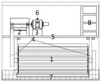
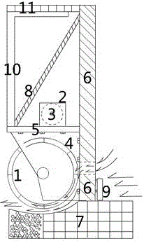
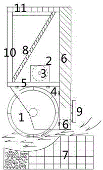
[0026] like figure 1 As shown: the sluice-back hydropower station described in this embodiment is mainly composed of a water turbine 1, a synchronous belt drive speed increaser 2, a generator 3, a sluice 6, a water turbine room 7, a speed-regulating sluice 9 and a station building. 6 can be any water gate of known equipment. A water inlet is provided at the bottom of the water gate 6, and a speed-regulating water gate 9 is arranged at the water inlet. "Patent, it is connected in front of the water gate 6 (facing the water), and is slidably connected with the water gate 6. On the back of the sluice 6 (the backside of the water) are connected a water turbine 1, a synchronous belt drive speed increaser 2, a generator 3 and a station building. The water turbine 1 is horizontally arranged in the station building, and the water pecking method is horizontal water pecking. Wha...


PUM


Abstract

The invention discloses a sluice back type hydropower station, which is characterized in that a water inlet is formed in a sluice (6), a hydropower station, which is mainly formed by a water turbine (1), a synchronous belt drive speed increaser (2), a generator (3), a water turbine chamber (7) and a station house, is arranged on the sluice (6), the water pecking manner of the water turbine (1) is transverse water pecking, and when the water turbine (1) rotates, only part of the water turbine and the overflowing water are in contact and work. According to the sluice back type hydropower station, the hydropower station is constructed on a control sluice, and the sluice equipment is provided two functions of power generation and control without influencing the existing function of water power control of the sluice. Construction of the hydropower station on the sluice is still pioneering, so that the construction field of the hydropower station is expanded, the construction cost is reduced and the sluice back type hydropower station is easy to implement. The large, medium and small sluice back type hydropower stations can be reconstructed and newly-constructed on all kinds of completed and newly-constructed sluice backs at bay, coast, river watercourses, canal systems, reservoirs, lakes and landscape water, and the application range is very wide.

Description

technical field [0001] The invention belongs to the technical field of low water head hydropower stations, and mainly relates to a sluice-back type hydropower station. It is widely applicable to hydroelectric power stations built on the backs of all kinds of sluices with a certain water supply and drainage flow that have been built or newly built in bays, seashores, river waterways, canal systems, reservoirs, lakes, and landscape waters. Background technique [0002] Hydropower is clean energy, renewable, non-polluting, low operating cost, and convenient for power peak regulation. Since ancient times, various sluices have been used in the development and utilization of water kinetic energy for collection, drainage, and flood control. However, looking at the sluices needed, there is no precedent for simultaneous use for power generation. Tracing it to its cause, there is direct relation with the structure of existing water turbine unit. The water turbine and the water...

Claims


Application Information

Patent Timeline
Patent Type & Authority Applications(China)
IPC IPC(8): F03B3/00F03B3/12
CPCF03B13/08Y02B10/50Y02E10/20
Inventor 梁士周
Owner 洛阳市四洲水能发电科技有限公司
Learn More