Heat energy electricity generation set with shale gas

A technology of thermal power generation and shale gas, which is applied in the direction of machines/engines, mechanical equipment, mechanisms for generating mechanical power, etc., can solve the problems of high shale gas transportation costs, short mining life of ore deposits, etc., and facilitate the transfer of mining areas , Conducive to development, high economical effect

Inactive Publication Date: 2015-05-06
任毛丁
View PDF4 Cites 2 Cited by
  • Summary
  • Abstract
  • Description
  • Claims
  • Application Information

AI Technical Summary

Problems solved by technology

[0003] In order to overcome the problems caused by the high cost of shale gas transportation and the short mining life of ore deposits encountered in the large-scale exploitation of shale gas, a special design is made to use shale gas combustion to generate a temperature difference between the two ends of the converter, so that the converter The thermal power generation device for swing power generation realizes the conversion of shale gas into electric energy on the spot, which can be integrated into the national grid nearby, and the device is easy to disassemble and assemble, and is easy to transfer

Method used


Image

  • Heat energy electricity generation set with shale gas
  • Heat energy electricity generation set with shale gas
  • Heat energy electricity generation set with shale gas

Examples


Embodiment Construction

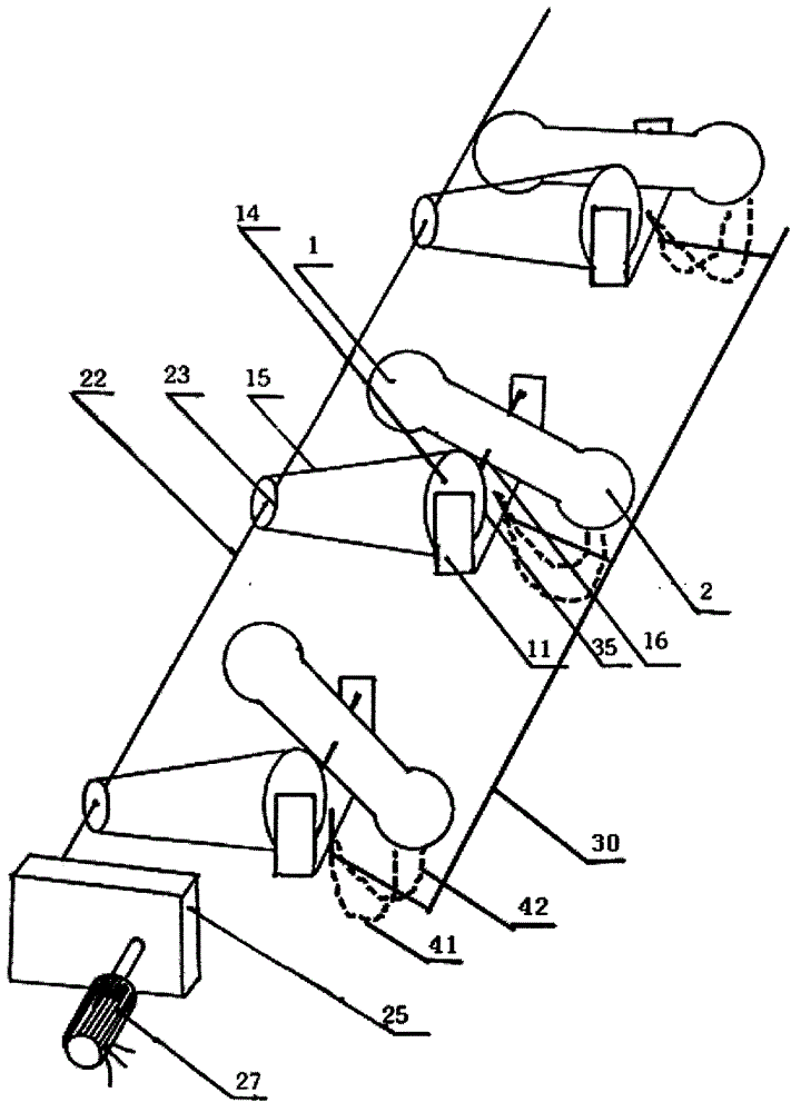
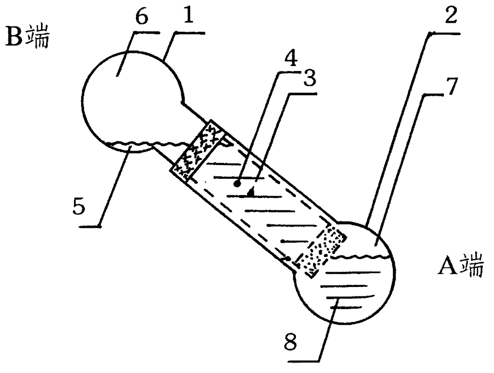
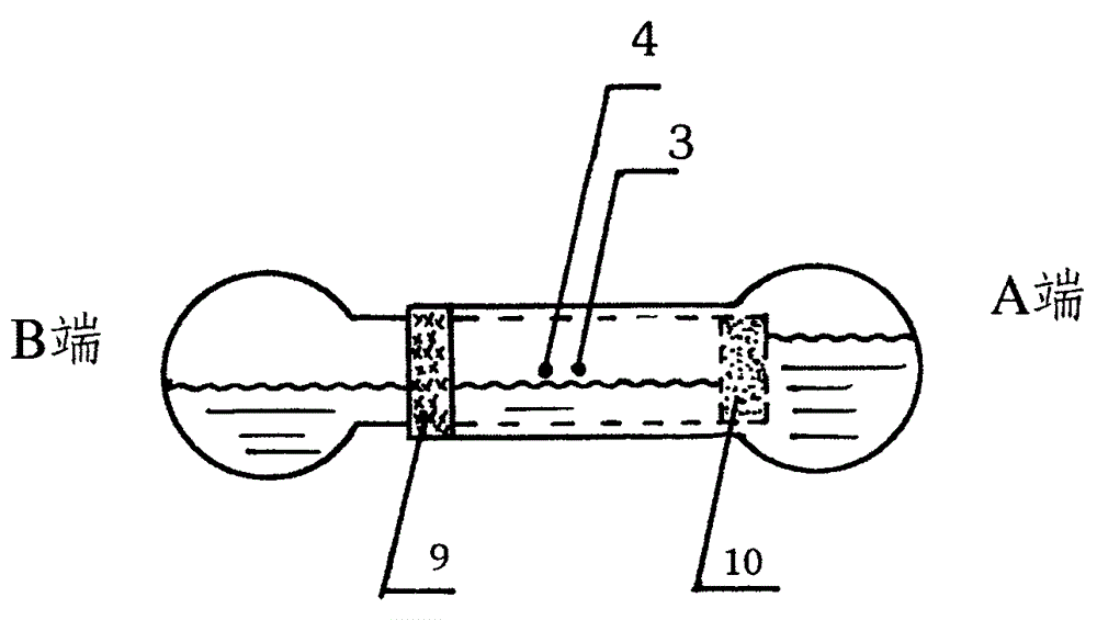
[0038] In this embodiment, the shale gas thermal power generation device consists of a thermal energy converter ( figure 2 ), ratchet drive mechanism ( Figure 4 ), power generation input device ( Figure 5 ) and other components. Insert the metal container (1) with a long ball neck and a small mouth into the metal container (2) with a long ball neck and a large mouth, and use a sealant (9) between the neck walls of the two pipes to connect (1) and (2) into a sealed whole, Inject B end liquid water (5) and A end liquid water (8) in advance, and place water-proof fabric (10) at (1) opening. Find the balance axis (3) and support axis (4) of the seal unit. The center of gravity is at the right side A end of (4), the A end is down, the B end is up, and the liquid level of the B end is higher than the water-proof fabric (10). When the main air supply switch antenna (34) contacts the main air supply switch contact (33), the main air supply switch (30) is turned on. The shale gas ...


PUM


Abstract

The invention relates to a heat energy electricity generation set with shale gas. The heat energy electricity generation set consists of a heat energy converter, a ratchet transmission mechanism, and an electricity generation input device, wherein the converter is a whole formed by embedding two long tube neck containers with one large ends and the other open ends and sealing the embedded part, a spacer is arranged in a tube to form two isolation spaces respectively containing liquid and gas, and the spacer allows gas to pass without allowing liquid to pass. A support shaft is arranged on the tube neck in a selective manner, so that the whole center of gravity is deflected to the lower end; the level surface of the liquid in an upper end part is higher than the spacer in height, a shale gas fire tray is ignited, so that an internal plus gas pressure difference is generated, the center of gravity moves to the upper end part along the liquid in the upper end, the lower end swings upwards, and the fire tray is extinguished. While in a level position, the internal gas pressure difference is zero, both ends swing in reverse directions, and the operation is circulated; the transmission mechanism is transmitted by a plurality of ratchet wheels running side by side and sprocket wheels to swing back and forth so as to become the intermittent rotation of the large sprocket wheel, and then to become the continuous rotation of a small sprocket wheel shaft, and after two-stage speed increasing, the continuous rotation is inputted in an electricity generator. The heat energy electricity generation set can be expanded to fields of using unconventional stone materials, such as mine gas, to perform electricity generation.

Description

technical field [0001] The invention belongs to the technical field of thermal power generation, and in particular relates to a thermal power generation device which utilizes shale gas combustion to generate a temperature difference at both ends of a converter to make the converter swing to generate electricity. Background technique [0002] The use of natural gas instead of coal for power generation is an important part of industrial adjustment and energy conservation and emission reduction, and fully meets the policy requirements of the country's long-term development. Shale gas refers to natural gas stored in cracks in shale formations below 500 meters underground. With the long-term large-scale exploitation of conventional fossil energy such as oil, natural gas, and coal, the reserves are decreasing day by day, and unconventional fossil energy such as shale gas and shale oil has been paid more and more attention. In the 1980s, the United States began to study new techno...

Claims


Application Information

Patent Timeline
Patent Type & Authority Applications(China)
IPC IPC(8): F03G7/08
CPCF03G7/08
Inventor 任毛丁
Owner 任毛丁
Why Eureka
Try Eureka