Oil and gas pipeline leakage positioning method based on sound wave amplitude attenuation model

A technology of acoustic wave amplitude and attenuation model, which is used in pipeline systems, gas/liquid distribution and storage, mechanical equipment, etc., can solve the problem that the applicability of leak location methods is not universal, the applicability of oil pipelines and gas pipelines is insufficient, and the calculation of leak location is increased. It can solve the problems of low positioning accuracy, low cost and avoid installation.

Active Publication Date: 2015-05-06
CHINA UNIV OF PETROLEUM (EAST CHINA)
View PDF10 Cites 30 Cited by
  • Summary
  • Abstract
  • Description
  • Claims
  • Application Information

AI Technical Summary

Problems solved by technology

[0010] (1) There is no unified formula for solving the sound wave propagation velocity that oil and gas pipeline leakage location depends on, and the applicability to oil pipelines and gas pipelines is insufficient, making the applicability of the leakage location method not universal. The reliability needs to be guaranteed, which increases the calculation amount of leak location
[0011] (2) The solution to the time difference for oil and gas pipeline leak location requires the use of GPS system to time the data signal collected by the acoustic sensor, which increases the cost of leak location on the one hand, and reduces the positioning accuracy on the other hand

Method used


Image

  • Oil and gas pipeline leakage positioning method based on sound wave amplitude attenuation model
  • Oil and gas pipeline leakage positioning method based on sound wave amplitude attenuation model
  • Oil and gas pipeline leakage positioning method based on sound wave amplitude attenuation model

Examples


Embodiment Construction

[0033] In order to make the object, technical solution and advantages of the present invention more clear, the present invention will be further described in detail below in conjunction with the examples. It should be understood that the specific embodiments described here are only used to explain the present invention, not to limit the present invention.

[0034] The application principle of the present invention will be further described below in conjunction with the accompanying drawings and specific embodiments.

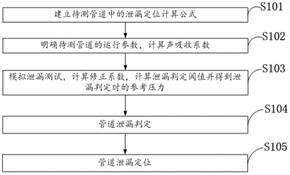
[0035] Such as figure 1 As shown, the oil and gas pipeline leakage location method based on the acoustic wave amplitude attenuation model in the embodiment of the present invention includes the following steps:

[0036] S101: Establish a calculation formula for leak location in the pipeline to be tested according to the acoustic wave amplitude attenuation model;

[0037]S102: Calculate the sound absorption coefficient according to the operating parameters of th...


PUM


Abstract

The invention discloses an oil and gas pipeline leakage positioning method based on a sound wave amplitude attenuation model. The oil and gas pipeline leakage positioning method comprises the following steps of establishing a leakage positioning computing formula in a to-be-tested pipeline; computing the sound absorbing coefficient; detecting the minimum detectable leakage amount or leakage hole diameter of the to-be-tested pipeline, performing the simulating leakage testing experiment at the upstream of a sensor at the head end of the to-be-tested pipeline, computing the correction coefficient according to the obtained amplitude, and further obtaining a leakage judging threshold value and the reference pressure during leakage judging; processing the signals collected by the sensors at the two ends of the to-be-tested pipeline, dividing by the reference pressure, and comparing the result and the leakage judging threshold value obtained by the simulating leakage testing experiment; when the leakage occurs, positioning the leakage of the pipeline according to the positioning formula. The oil and gas pipeline leakage positioning method has the advantages that by computing the sound absorbing coefficient and the correction coefficient in the leakage positioning computing formula, the leakage is detected and positioned; the mounting of a GPS (global positioning system) clock is avoided, the cost is low, the sensitivity is high, and the suitability for the oil and gas pipeline is high.

Description

technical field [0001] The invention belongs to the technical field of pipeline safety monitoring, in particular to an oil and gas pipeline leakage location method based on an acoustic wave amplitude attenuation model. Background technique [0002] When the oil and gas pipeline leaks, the fluid medium flows out of the pipeline, and the pressure in the pipeline drops suddenly to generate sound waves. According to the classification of the acoustic wave sensor, the sound wave can be divided into the sound collected by the audio sensor, the vibration signal collected by the acceleration sensor, and the dynamic pressure sensor. The dynamic pressure wave collected by the sensor has different waveform presentation methods depending on the sensor. The former two are suitable for short-distance pipelines, and the dynamic pressure wave is suitable for long-distance oil and gas pipelines. The sound wave propagates along the medium in the pipe and is collected by the dynamic pressure s...

Claims


Application Information

Patent Timeline
Patent Type & Authority Applications(China)
IPC IPC(8): F17D5/06
Inventor 刘翠伟李玉星孟令雅胡其会韩辉张玉乾刘光晓钱昊铖
Owner CHINA UNIV OF PETROLEUM (EAST CHINA)
Why Eureka
Try Eureka