Hot blast stove

A technology of hot blast stove and hot blast channel, which is applied in the direction of air heater, fluid heater, lighting and heating equipment, etc. It can solve the problems of affecting the use environment, polluting the environment, and producing a large amount of dense smoke, so as to improve thermal efficiency, reduce pollution, The effect of simple structure

Active Publication Date: 2015-05-06
江苏麦信环能科技有限公司
View PDF5 Cites 1 Cited by
  • Summary
  • Abstract
  • Description
  • Claims
  • Application Information

AI Technical Summary

Problems solved by technology

However, there is a problem in the existing biomass hot blast stove, that is, a large amount of thick smoke will be generated during use, which not only pollutes the environment, but also affects the use environment, so its structure needs to be further improved

Method used


Image

  • Hot blast stove
  • Hot blast stove
  • Hot blast stove

Examples


Embodiment 1

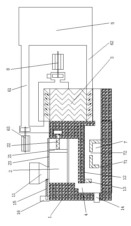
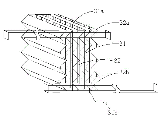
[0026] Such as Figure 1 to Figure 2 As shown, a hot blast stove includes a housing 1, the housing 1 is provided with a refueling port 11, the housing 1 is provided with a combustion chamber 2 and a heat exchanger 3, the combustion chamber 2 is provided with an air inlet, and the heat The exchanger 3 is composed of flue gas passages 31 and hot air passages 32 arranged alternately and in a continuous bending structure. The flue gas passages 31 are closed on both sides and open up and down. Road 4 is connected, and the upper opening 31a of the flue gas passage 31 cooperates with the first induced draft fan 8; the two sides of the hot air passage 32 are closed, and the upper and lower ends are also closed, and the upper and lower ends of the hot air passage 32 sides are respectively provided with upper openings 32a and The lower opening 32b, the opening of the hot air channel 32 communicates with the air channel, and the air channel is provided with a second induced draft fan 63;...

Embodiment 2

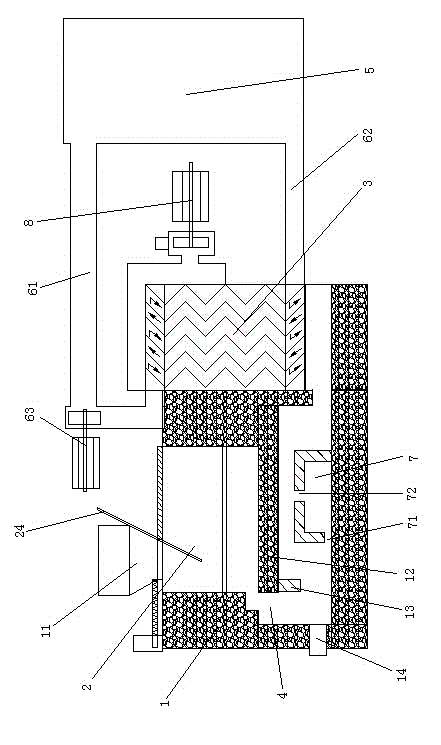
[0046] Such as image 3 As shown, the structure of the hot blast stove in this embodiment is similar to that of the hot blast stove in Embodiment 1, the difference is that: the bottom of the fuel inlet 11 of the hot blast stove is obliquely provided with a charging regulating plate 24, and the charging regulating plate The bottom of 24 stretches in the combustion chamber 2. The purpose of adjusting the amount of fuel added is achieved by twitching the feeding regulating plate 24 obliquely, and the structure is simpler and more practical.


PUM


Abstract

The invention discloses a hot blast stove which comprises a shell, wherein a fuel feeding hole is formed in the shell; a combustion chamber and a heat exchanger are arranged in the shell; an air inlet is formed in the combustion chamber; the heat exchanger is composed of a flue gas channel and a hot air channel which are arranged alternatively and are both in a continuous bending structure; two sides of the flue gas channel are closed; upper and lower ends of the flue gas channel are opened; the combustion chamber is communicated with the lower opening of the flue gas channel through a flame path; the upper opening of the flue gas channel is fitted with a first induced draft fan; two sides of the hot air channel are closed; upper and lower ends of the hot air channel are also closed; an upper opening and a lower opening are respectively formed in upper and lower ends of the side of the hot air channel; the openings of the hot air channel are fitted with an air flue in a communication manner; a second induced draft fan is arranged on the air flue. The hot blast stove disclosed by the invention is simple in structure and convenient to use; the continuous bending structure increases the passing time of fluid in the heat exchanger and increases the superficial areas of the flue gas channel and the hot air channel, so that the heat exchanging is more fully, and the heat efficiency of the hot blast stove is greatly improved.

Description

technical field [0001] The invention relates to heating equipment, in particular to a hot blast stove, in particular to a hot blast stove using biomass as fuel. Background technique [0002] At present, there are only two types of hot blast stoves appearing on the market: one is vertical cylinder, double-layer standpipe and square horizontal straight tube hot blast stove; the other is horizontal straight tube back-fired hot blast stove. They have the disadvantages of large volume, heavy weight, and large floor space; in addition, most of the existing hot blast stoves use coal or gas as fuel, and the use cost is relatively high. Furthermore, the existing hot blast stoves have low thermal efficiency, and most of them use heat pipes for heat exchange, which causes uneven heating, which easily causes local high temperature and causes the heat pipes to age and burn through. [0003] There are hot blast stoves using biomass as fuel on the market now. Biomass refers to various or...

Claims


Application Information

Patent Timeline
Patent Type & Authority Applications(China)
IPC IPC(8): F24H3/06F24H9/00
Inventor 陈立德
Owner 江苏麦信环能科技有限公司
Why Eureka
Try Eureka