Automatic dip angle compensated contact electromagnetic induction waterproof distance measuring pen

A technology of electromagnetic induction and distance measuring pen, which is applied in the direction of using electromagnetic means, measuring devices, and electric devices. It can solve the problems of high power consumption, short battery life, and inconvenient portability, and achieve the effect of compensating errors.

Inactive Publication Date: 2015-05-06
何远薇 +1
View PDF8 Cites 4 Cited by
  • Summary
  • Abstract
  • Description
  • Claims
  • Application Information

AI Technical Summary

Problems solved by technology

[0002] People live at home, travel abroad, enterprise product design, field exploration, army training, combat, etc. need to frequently measure the length of straight lines and curves on the map or in the actual space; the current common method of measuring the length of the curve is to use a The rope fits the shape of the curve, and then straightens the rope to measure its length. The disadvantages of this method are that it is not easy to carry, the accuracy is low, and the measurement results have large errors.
At the same time, there are also some distance measuring products on the market, which respectively adopt mechanical, light wheel, and photoelectric distance measuring methods; among them, the mechanical distance measuring equipment uses a roller to move along the curve to be measured, and after a series of gears reduce the speed, Drive the pointer to display numbers (patent number: CN200920052864.2). This tool is large in size, inconvenient to reset, inaccurate in accuracy, and its complex and precise mechanical structure results in poor mechanical shock resistance; the optical wheel distance measurement method is used A grating wheel moves along the predicted curve, and the laser counts the grating to obtain the measured distance (Patent No.: CN99248685.8). The grating of this tool cannot be made dense enough due to technological constraints, resulting in poor measurement accuracy, and Because the light grid is small, it is easy to be damaged during use and cause the equipment to be scrapped
At the same time, due to the change of the angle of the user's wrist during the movement of the above contact pen distance measuring equipment, the body of the pen will tilt with the movement of the user's hand and move in an arc around the axis of the contact wheel, thus causing the contact wheel to move outside The relative displacement caused by the non-contact wheel rolling on the surface of the measured object occurs on the surface relative to the pen body, which causes the measured data to change and cause errors
However, photoelectric equipment needs to continuously emit light pulses during the measurement process and use photoreceptors to receive them, and at the same time use a single-chip microcomputer to continuously count the signal changes generated by the photoreceptors to calculate the displacement of the pen relative to the surface of the measured object (patent application number: CN201310450737. 9), this method needs to read the change of the reflected light of the measured surface received by the photoreceptor, and the use on the surface of the measured object with smooth surface and good identity is greatly limited, and the photoelectric sensor module used It needs to transmit, receive and solve light pulses, resulting in high power consumption and short battery life, which is not conducive to energy saving, environmental protection and long-term use
At the same time, the above distance measuring methods all have the disadvantages that they are not convenient for waterproofing and cannot be used underwater, and the scope of application is limited.

Method used


Image

  • Automatic dip angle compensated contact electromagnetic induction waterproof distance measuring pen
  • Automatic dip angle compensated contact electromagnetic induction waterproof distance measuring pen
  • Automatic dip angle compensated contact electromagnetic induction waterproof distance measuring pen

Examples


Embodiment Construction

[0026] The present invention will be further described in detail below in conjunction with the accompanying drawings and specific embodiments. .

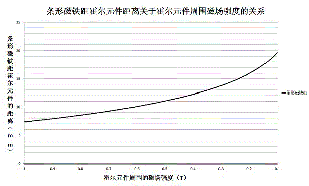
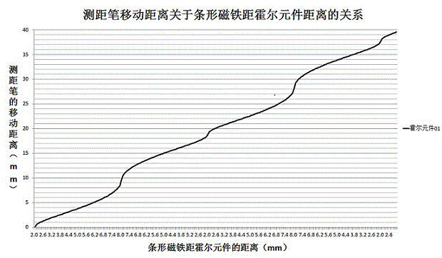
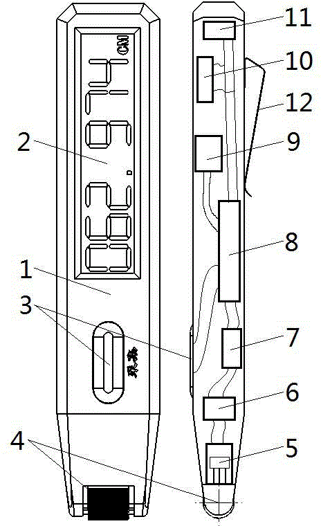
[0027] combine figure 1 As shown, the present invention includes a waterproof casing 1, a liquid crystal digital display panel 2, an acquisition button 3, a contact wheel shaft 4, a Hall element 5, a signal amplifier 6, an analog-to-digital converter 7, a microprocessor 8, and a digital single-axis gyroscope 9. Digital display panel driver 10, battery 11, and back clip 12, wherein the electromagnetic induction distance measuring head is composed of the contact axle 4 and the Hall element 5, and is composed of the Hall element 5, the signal amplifier 6, and the analog-to-digital converter 7 distance measuring circuit; the front end of the waterproof casing 1 is provided with a contact wheel shaft 4, the upper surface is inlaid with a collection button 3, a liquid crystal digital display panel 2, and a back clip 12 is fixed on the lo...


PUM


Abstract

The invention relates to an automatic dip angle compensated contact electromagnetic induction waterproof distance measuring pen comprising a waterproof housing (1), a liquid crystal display panel (2), a collection key (3), a contact wheel shaft (4), a hall element (5), a signal amplifier (6), a analog-digital converter (7), a micro processor (8), a digital single-axis gyroscope (9), a display panel drive device (10), a battery (11) and a back clamp (12). The collection key (3) is pressed, the contact wheel shaft (4) rolls on the surface of an object to be measured, the distance between a stripped magnet and the hall element (5) changes regularly, and the strength of the magnetic field surrounding the hall element (5) changes regularly; according to the hall principle, the distance amount is calculated according to the change amount of hall potential difference through the micro processor (8), the change amount of the dip angle of the waterproof housing (1) detected by the digital single-axis gyroscope (9) is combined, the error caused by the change of the dip angle in the measuring process is compensated, and counting is performed through the liquid crystal display panel (2) to achieve the distance measuring purpose. The pen is reasonable in structure, accurate in measurement, convenient to use, high in adaptability, energy saving and environment-friendly.

Description

technical field [0001] The invention relates to a high-precision contact-type electronic distance-measuring device, in particular to a contact-type electromagnetic induction waterproof distance-measuring pen with a waterproof function, which uses a Hall element and can automatically compensate the inclination angle of the pen body. Background technique [0002] People live at home, travel abroad, enterprise product design, field exploration, army training, combat, etc. need to frequently measure the length of straight lines and curves on the map or in the actual space; the current common method of measuring the length of the curve is to use a The rope fits the shape of the curve, and then the rope is straightened to measure its length. The disadvantages of this method are that it is not easy to carry, the accuracy is low, and the measurement results have large errors. At the same time, there are also some distance measuring products on the market, which respectively adopt me...

Claims


Application Information

Patent Timeline
Patent Type & Authority Applications(China)
IPC IPC(8): G01B7/02
Inventor 陈其昌何远薇
Owner 何远薇
Why Eureka
Try Eureka