Multi-wavelength multiplexing/demultiplexing parallel light receiving/emitting component

A technology for optical transceiver components and optical launch components, applied in the field of optical communication, can solve the problem that parallel optical transceiver components cannot be compatible with a single fiber network, and achieve the effect of saving fiber costs and meeting high-speed bandwidth requirements.

Inactive Publication Date: 2015-05-06
WUHAN TELECOMM DEVICES
View PDF5 Cites 33 Cited by
  • Summary
  • Abstract
  • Description
  • Claims
  • Application Information

AI Technical Summary

Problems solved by technology

[0004] The purpose of the embodiment of the present invention is to provide a multi-wavelength multiplexing/demultiplexing parallel optical transceiver c

Method used


Image

  • Multi-wavelength multiplexing/demultiplexing parallel light receiving/emitting component
  • Multi-wavelength multiplexing/demultiplexing parallel light receiving/emitting component
  • Multi-wavelength multiplexing/demultiplexing parallel light receiving/emitting component

Examples


Embodiment 1

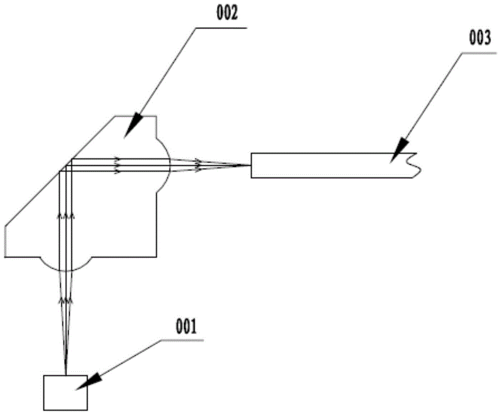
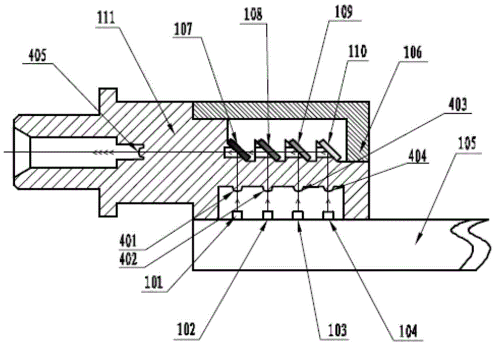
[0068] Embodiment 1 provided by the present invention is the first embodiment of a multi-wavelength multiplexing / demultiplexing parallel optical emission component provided by the present invention, such as image 3 Shown is a schematic structural diagram of the first embodiment of a multi-wavelength multiplexing / demultiplexing parallel light emitting component provided by the present invention, which is represented by image 3It can be seen that in the embodiment of the multi-wavelength multiplexing / demultiplexing parallel optical transceiver component provided by the present invention:

[0069] The corresponding working bands of the first laser emitting chip 101, the second laser emitting chip 102, the third laser emitting chip 103 and the fourth laser emitting chip 104 are respectively 820nm, 850nm, 880nm, 910nm, or other wavelengths and wavelength intervals near 850nm .

[0070] The first collimating lens 401 and the second collimating lens respectively corresponding to t...

Embodiment 2

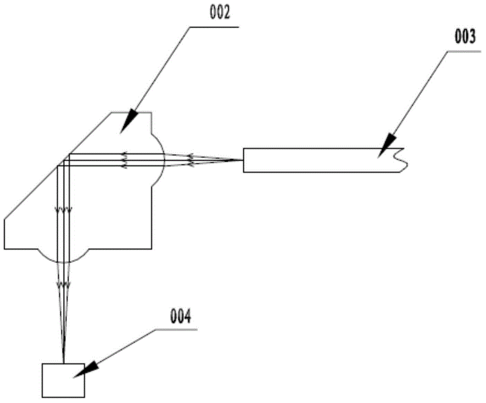
[0078] Embodiment 2 provided by the present invention is the first embodiment of a multi-wavelength multiplexing / demultiplexing parallel optical receiving component provided by the present invention. The first embodiment of the parallel optical receiving component is the same as the parallel optical receiving component provided by the present invention. The first embodiment of the launch assembly is used in conjunction with, as Figure 4 Shown is a schematic structural diagram of the first embodiment of a multi-wavelength multiplexing / demultiplexing parallel light emitting component provided by the present invention, which is represented by Figure 4 It can be seen that in the embodiment of the multi-wavelength multiplexing / demultiplexing parallel optical transceiver component provided by the present invention:

[0079] The sixth collimating lens 406 is used to shape the light beam transmitted by the optical fiber into collimated light.

[0080] The first wavelength division ...

Embodiment 3

[0087] The third embodiment provided by the present invention is the second embodiment of a multi-wavelength multiplexing / demultiplexing parallel optical emission component provided by the present invention, such as image 3 Shown is a schematic structural diagram of the second embodiment of a multi-wavelength multiplexing / demultiplexing parallel light emitting assembly provided by the present invention, the second embodiment of the light emitting assembly is the same as the first embodiment of the light emitting assembly provided by the present invention The structure and principle of an embodiment are the same, the corresponding working bands of the first laser emitting chip 101, the second laser emitting chip 102, the third laser emitting chip 103 and the fourth laser emitting chip 104 are 1250nm, 1280nm, 1310nm, 1340nm, or Other wavelengths and wavelength intervals around 1310nm. The optical filters 107-110 are multiplexing & demultiplexing optical filters corresponding to...


PUM


Abstract

The invention is suitable for the optical communication field and discloses a multi-wavelength multiplexing/demultiplexing parallel light receiving/emitting component. Four laser emitting chips or detector receiving chips arranged on a PCB circuit board are located on the same straight line; four collimating lenses are respectively located above the four laser emitting chips or detector receiving chips, and top light spots are aligned to the centers of photosensitive surfaces of the four detector receiving chips or the four laser emitting chips; four wavelength division multiplexing/demultiplexing optical filters are respectively arranged above the four collimating lenses and parallel to each other, the reflecting surfaces face to the downside, and the angle between each reflecting surface and the PCB circuit board is 45 degrees; a fifth collimating lens is located at one side of the reflecting surface of each wavelength division multiplexing/demultiplexing optical filter, and the optical paths between the fifth collimating lenses and the wavelength division multiplexing/demultiplexing optical filters are vertical to the optical paths between the wavelength division multiplexing/demultiplexing optical filters and laser emitting chips or detector receiving chips. Several channels only need one optical fiber to perform communication transmission, and the optical fiber cost is greatly saved.

Description

technical field [0001] The invention belongs to the field of optical communication, in particular to a multi-wavelength multiplexing / demultiplexing parallel optical transceiver component. Background technique [0002] With the comprehensive popularization of the information industry, the explosive growth of the global data volume, the construction of global data centers is in full swing. Parallel optical modules are favored by the industry due to their large communication capacity and low energy consumption, and have developed rapidly in recent years. The parallel optical module refers to the realization of one-to-one transmission of multi-channel lasers and multi-channel detectors through multiple optical fibers in one module. The low power consumption brought about by device integration and miniaturization makes the parallel optical module generate and dissipate much less heat than multiple discrete devices. Parallel optical modules mainly rely on high-density integratio...

Claims


Application Information

Patent Timeline
IPC IPC(8): G02B6/42H04B10/40
CPCG02B6/4204G02B6/4215G02B6/4246H04B10/40
Inventor 郑盼余向红徐红春刘成刚林雪枫
Owner WUHAN TELECOMM DEVICES
Why Eureka
Try Eureka