Broadband high-gain double-circle polarized patch antenna

A dual circularly polarized, patch antenna technology, applied in the direction of the antenna, antenna grounding device, antenna support/installation device, etc., to achieve the effect of wide bandwidth, high gain, and convenient connection

Active Publication Date: 2015-05-06
SOUTHEAST UNIV
View PDF1 Cites 21 Cited by
  • Summary
  • Abstract
  • Description
  • Claims
  • Application Information

AI Technical Summary

Problems solved by technology

However, in the prior art, antennas rarely have wide bandwidth, high gain

Method used


Image

  • Broadband high-gain double-circle polarized patch antenna
  • Broadband high-gain double-circle polarized patch antenna
  • Broadband high-gain double-circle polarized patch antenna

Examples


Embodiment Construction

[0023] The present invention will be further described below in conjunction with the accompanying drawings.

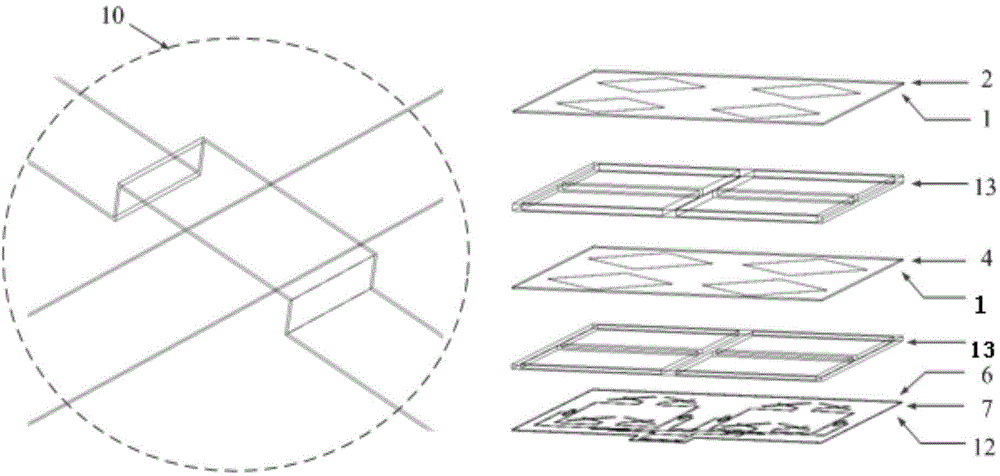
[0024] like figure 1 A wide-band high-gain dual circularly polarized patch antenna is shown, including an upper dielectric substrate 2, a middle dielectric substrate 4, and a lower dielectric substrate 7 placed sequentially from top to bottom; the upper dielectric substrate 2, the middle dielectric substrate A dielectric frame 13 is used for isolation and support between the sheet 4 and the lower dielectric substrate 7;

[0025] Square patch arrays are arranged on the lower surfaces of the upper dielectric substrate 2 and the middle dielectric substrate 4; each square patch array includes four square units, and the four square units are arranged in two rows and two columns, and each The square units are placed at 45 degrees, and the patch spacing of each square unit is 0.73*λ 0 , where λ 0 is the air wavelength. The floor layer 6 is located on the upper surface of ...


PUM


Abstract

The invention discloses a broadband high-gain double-circle polarized patch antenna. The broadband high-gain double-circle polarized patch antenna comprises a floor layer, a feed network, square patch arrays, an upper dielectric substrate, a middle dielectric substrate and a lower dielectric substrate, wherein the upper dielectric substrate, the middle dielectric substrate and the lower dielectric substrate are sequentially arranged from top to bottom and are supported separably through dielectric frames. The square patch arrays are adhered to the lower surfaces of the upper dielectric substrate and the middle dielectric substrate. Each square patch array comprises four square units in two-row two-column arrangement. The floor layer is positioned on the upper surface of the lower dielectric substrate. The feed network is etched on the lower surface of the lower dielectric substrate. Eight radiant gaps are etched on the floor layer. The feed network comprises a directional coupler, six power dividers and an air bridge. The feed network divides an input signal into eight channels of signals, feeds the signals into the radiant gaps and feeds electricity upwardly to the square patch arrays through the radiant gaps, and finally, an antenna radiation effect is achieved through middle and upper radiation. The broadband high-gain double-circle polarized antenna is achieved by the aid of a printed circuit process.

Description

technical field [0001] The invention relates to a wide-band high-gain dual-circular polarization patch antenna, which belongs to the field of wireless communication. Background technique [0002] With the rapid development of wireless communication, radio frequency identification, radar and other technologies and the expansion of application scope, as the front end of microwave and millimeter wave systems, antennas need to work in various polarization modes and harsh weather conditions, and the single polarization mode has become more and more difficult. It is increasingly unable to meet the needs of practical applications. [0003] Circularly polarized waves are superimposed by linearly polarized waves with equal amplitude and phase difference of 90 degrees; linearly polarized waves can also be superimposed by circularly polarized waves with different hand directions. Therefore, linearly polarized waves with different orientations can be received by circularly polarized an...

Claims


Application Information

Patent Timeline
IPC IPC(8): H01Q1/38H01Q1/50H01Q1/48H01Q1/12H01Q15/24
Inventor 张彦庄建兴洪伟王海明
Owner SOUTHEAST UNIV
Why Eureka
Try Eureka