Island microgrid multi-inverter control system with active filtering function and working method thereof
A control system and inverter technology, which is applied in the parallel control of multiple inverters in an islanded microgrid and in the field of distributed power generation. And other issues
- Summary
- Abstract
- Description
- Claims
- Application Information
AI Technical Summary
Problems solved by technology
Method used
Image
Examples
Embodiment 1
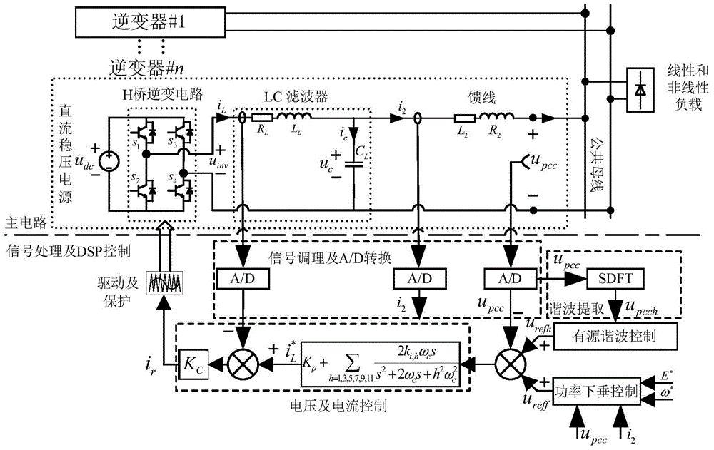
[0076] An island microgrid multi-inverter control system with active filtering function, including several parallel inverters, linear and nonlinear loads, several parallel inverters connected to a common bus, and the common bus is also connected to the Linear and nonlinear loads, several parallel inverters, the linear and nonlinear loads form an independent microgrid; the inverter includes a main circuit, signal processing and DSP control, the main circuit includes a DC stabilized power supply, H-bridge inverter circuit, LC filter, feeder, the H-bridge inverter circuit includes S 1 -S 4 Four power switch tubes, the DC stabilized power supply, the H-bridge inverter circuit, the LC filter, and the feeder are connected in sequence; the signal processing and DSP control include signal conditioning and A / D conversion, Harmonic extraction, active harmonic control, power droop control, voltage and current control, drive and protection; the signal conditioning and A / D conversion are ...
Embodiment 2
[0079] According to the control system described in Embodiment 1, it is further defined that the DC stabilized power supply is connected to both ends of the input side of the H-bridge inverter circuit, and the midpoints of the left and right bridge arms of the H-bridge inverter circuit are respectively A current tie line is drawn out, the current tie line is connected to the inductance current input end and the capacitor current output end of the LC filter, and the tie lines drawn from both ends of the capacitor of the LC filter are connected to the common bus through the feeder line.
[0080] The control system described in embodiment 1 or 2 is as figure 1 shown.
Embodiment 3
[0082] According to the working method of the control system described in embodiment 1 or 2, the specific steps include:
[0083] (1) At the starting point of each sampling period, signal conditioning and A / D conversion are started, and the inverter feeder grid-connected terminal voltage u pcc Sampling, through harmonic extraction, and sliding window Fourier transform, to obtain the hth common bus harmonic voltage u pcch , and then through active harmonic control, the specific harmonic component u of the reference output voltage of the inverter is output refh ; Active harmonic control calculation formula is:
[0084] u refh = K G Σ h = 3,5,7,9,11 G h u pcch
[0085] Among them, G h is the hth harmonic voltage feedback coefficient; K G is th...
PUM
 Abstract
Description
Claims
Application Information
 - R&D
- Intellectual Property
- Life Sciences
- Materials
- Tech Scout
- Unparalleled Data Quality
- Higher Quality Content
- 60% Fewer Hallucinations
Browse by: Latest US Patents, China's latest patents, Technical Efficacy Thesaurus, Application Domain, Technology Topic, Popular Technical Reports.
© 2025 PatSnap. All rights reserved.Legal|Privacy policy|Modern Slavery Act Transparency Statement|Sitemap|About US| Contact US: help@patsnap.com


