Method and device for controlling power-on flow of multi-branch battery energy storage system

A battery energy storage system, energy storage system technology, applied in battery circuit devices, circuit devices, secondary battery charging/discharging, etc., can solve the problem of system reliability reduction, affecting the rescue effect, and the reliability of lithium-ion battery energy storage systems. Reduced performance and other issues, to improve reliability and system stability

Active Publication Date: 2015-05-06
BEIJING ELECTRIC VEHICLE
View PDF4 Cites 16 Cited by
  • Summary
  • Abstract
  • Description
  • Claims
  • Application Information

AI Technical Summary

Problems solved by technology

[0004] The disadvantages of the above-mentioned existing lithium-ion battery energy storage systems are: after a single-cell or node open-circuit fault occurs, due to the branchless structure, the battery system as a whole will cut off the external high-voltage output, and it is impossible to realize

Method used


Image

  • Method and device for controlling power-on flow of multi-branch battery energy storage system
  • Method and device for controlling power-on flow of multi-branch battery energy storage system
  • Method and device for controlling power-on flow of multi-branch battery energy storage system

Examples


Example Embodiment

[0043] Embodiment one

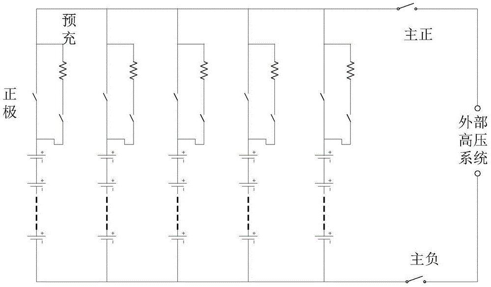
[0044] The schematic structural diagram of a lithium-ion battery energy storage system provided in this embodiment is as follows: figure 1 As shown, the lithium-ion battery energy storage system is composed of several branches connected in parallel, each branch is composed of several groups of battery modules connected in series, and the battery modules are composed of battery cells connected in series and parallel. Each branch has an independent relay and pre-charging equipment. After the branch is connected in parallel, it is connected to the external high-voltage system through two relays, the main positive and the main total negative. When different branches are in a state of voltage balance, each branch needs to complete the power-on action. When each branch is in an unbalanced state before power-on, the system obtains the current charging and discharging demand through the man-machine interface, and determines the power-on process of the branch a...

Example Embodiment

[0061] Embodiment two

[0062] When the MBCU determines that a branch is faulty based on the status information reported by the S-BCU of each branch, it will issue a zero power request to the external high-voltage system, and disconnect the relay of the faulty branch after reaching zero power, and a fault will occur branch removed. Since each branch is in parallel state, removing the failed branch will not affect other branches. After removing the faulty branch, restore the charging and discharging power of the system.

Example Embodiment

[0063] Embodiment three

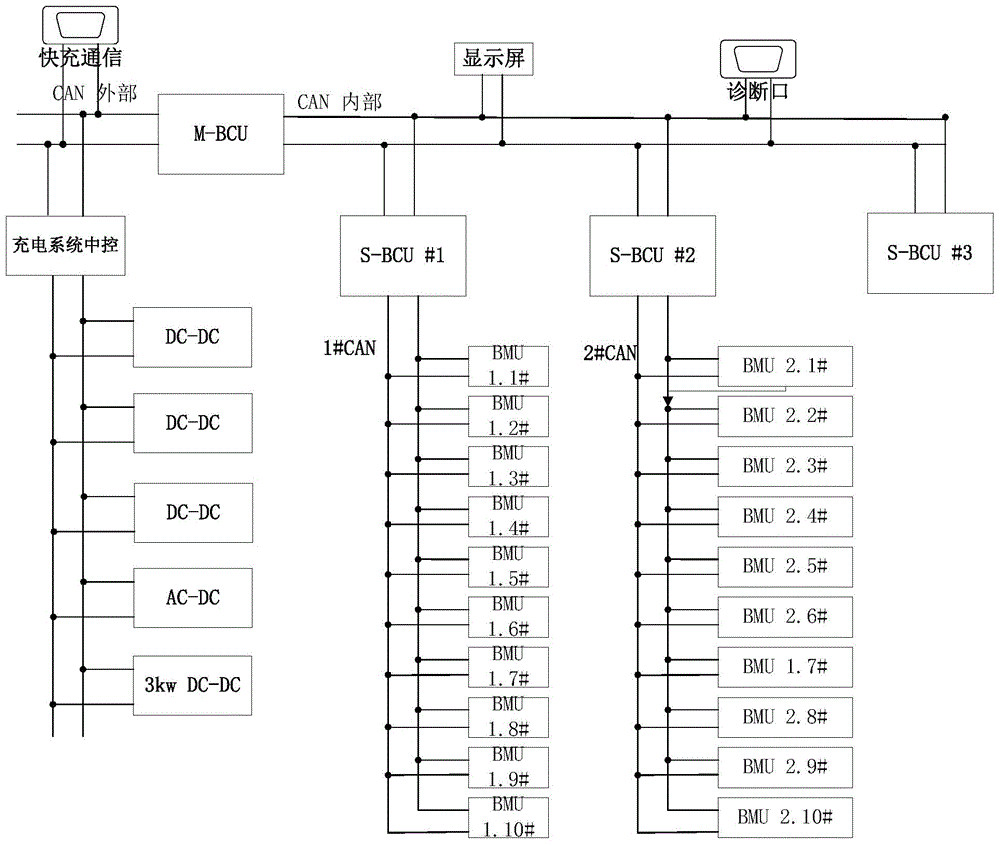
[0064] A schematic structural diagram of a power-on process control device for a multi-branch battery energy storage system provided in this embodiment is as follows: Figure 4 As shown, including: MBCU41, S-BCU42 of each branch and BMU43 of each battery module;

[0065] The S-BCU41 of each branch is used to report the state information of each branch to the MBCU, and the state information includes the voltage of each branch;

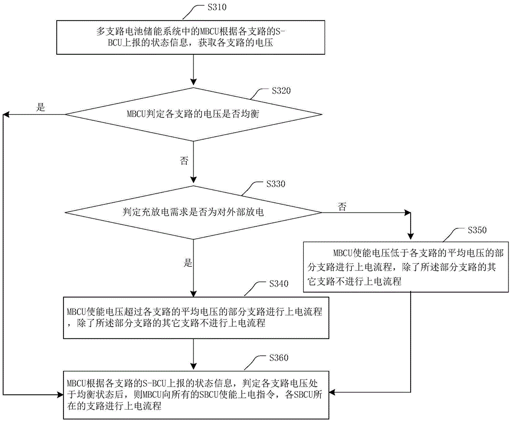
[0066] The MBCU42 is used to obtain the voltage of each branch according to the state information reported by the S-BCU of each branch, and to obtain the current charge and discharge demand of the battery energy storage system when it is determined that the voltage of each branch is unbalanced; When the charge and discharge requirement is for external discharge, the power-on process is performed on some branches whose voltage exceeds the average voltage of each branch, and the other branches except the part of the branch do no...


PUM


Abstract

The invention provides a method and a device for controlling the power-on flow of a multi-branch battery energy storage system. The method mainly comprises the following steps: an MBCU obtains the voltage of each branch according to state information reported by the S-BCU of each branch, the MBCU enable the power-on flow of partial branches of which the voltages exceed the average voltage of the various branches upon judging the imbalance of the voltages of the various branches and when a charging/discharging request is external discharging, and when the charging/discharging request is external charging, the MBCU enables the power-on flow of partial branches of which the voltages are lower than the average voltage of the various branches. According to the method, when the voltages of the branches are in an imbalance state, partial unbalanced branches are enabled to enter the power-on flow firstly by use of the MBCU, and each branch is powered on in different time so that the system stability can be improved. As a plurality of branches connected in parallel, the branches out of order can be flexibly removed without affecting the work of other branches, and therefore, the reliability of the battery energy storage system is improved.

Description

technical field [0001] The present invention relates to the technical field of battery energy storage systems, in particular to a method and device for controlling a power-on process of a multi-branch battery energy storage system. Background technique [0002] At present, the existing lithium-ion battery energy storage system is a single-branch series energy storage system. The capacity of the series-connected modules is realized through the series-parallel connection of the monomers. The single-branch series energy storage system communicates with the external High voltage system connection. [0003] Since the lithium-ion battery energy storage system has a large demand for capacity, in a single-branch series energy storage system, more cells are required to meet the demand through series-parallel connection, and the increased number of cells increases the probability of failure. [0004] The disadvantages of the above-mentioned existing lithium-ion battery energy storage...

Claims


Application Information

Patent Timeline
IPC IPC(8): H02J7/00H01M10/44
CPCH02J3/28
Inventor 秦兴权贺中玮梁瑞
Owner BEIJING ELECTRIC VEHICLE
Why Eureka
Try Eureka