Direct-current offset calibration method and device

A current and current compensation technology, applied in the field of receivers, can solve problems such as not very suitable for receiver applications, slow calibration convergence speed, etc., and achieve the effect of fast convergence speed and simple circuit structure

Active Publication Date: 2015-05-06
SANECHIPS TECH CO LTD
View PDF6 Cites 2 Cited by
  • Summary
  • Abstract
  • Description
  • Claims
  • Application Information

AI Technical Summary

Problems solved by technology

Each of the above elimination methods can achieve mismatch elimination, but they are all based on dynamic calibration, which has the problem of slow calibration convergence and is not very suitable for receiver applications.

Method used


Image

  • Direct-current offset calibration method and device
  • Direct-current offset calibration method and device
  • Direct-current offset calibration method and device

Examples


Embodiment Construction

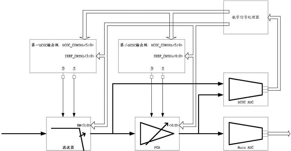
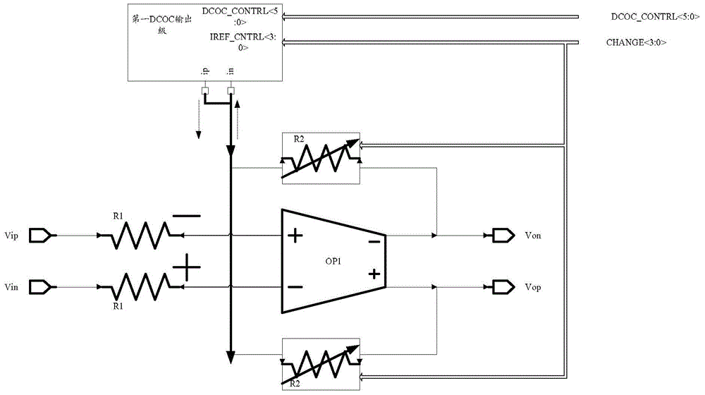
[0027] Common DC mismatch elimination methods include "input mismatch storage", "output mismatch storage", "pre-amplification", "negative feedback loop", etc. These methods have their own problems when directly applied to direct conversion receivers. For example, the methods of "input mismatch storage", "pre-amplification" and "output mismatch storage" require the support of a clock signal, and require the circuit to disconnect the input signal when measuring the mismatch voltage, which is not in line with the receiver For the "negative feedback loop" method, the circuit structure of this method is very simple, and it will have great advantages in power consumption and area, but its working speed is slow, and the output loss of compensation The distribution voltage range is limited, especially for the mismatch of the circuit receiving the calibration signal and the previous mismatch of the circuit, the "negative feedback loop" method is powerless. The above-mentioned several i...


PUM


Abstract

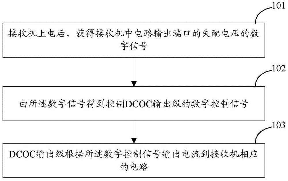
The invention discloses a DCOC (direct-current offset calibration) method. After a receiver is electrified, digital signals of offset voltage of a circuit output port in the receiver are acquired, digital control signals controlling a DCOC output stage are acquired through the digital signals, and current is outputted to a corresponding circuit of the receiver by the DCOC output stage according to the digital control signals. The invention further discloses a direct-current offset calibration device.

Description

technical field [0001] The invention relates to receiver technology, in particular to a method and device for eliminating direct current mismatch. Background technique [0002] In the receiver, since the receiver needs to amplify the received weak signal, the gain of the receiver is very high, usually reaching 60dB-80dB. High-gain circuits usually have a large DC mismatch due to circuit mismatch, which is the case for receivers. The DC mismatch of the receiver will cause the circuit of the receiver to enter an abnormal working state, which will affect the performance of the circuit, and even the function, such as the EVM and gain of the receiver, etc. DC mismatch cancellation (DCOC) is designed to solve this problem produced. [0003] There are many ways to implement DCOC, such as input mismatch storage, output mismatch storage, pre-amplification, negative feedback loop, etc. Each of the above elimination methods can achieve mismatch elimination, but they are all based on...

Claims


Application Information

Patent Timeline
Patent Type & Authority Applications(China)
IPC IPC(8): H04B1/16
CPCH04B1/16H04B1/30H04L27/20H04B1/12
Inventor 谢豪律王勇涛王倬遥付慕衡
Owner SANECHIPS TECH CO LTD
Why Eureka
Try Eureka