Low-strain dynamic monitoring device for underwater pile foundation

A low-strain, dynamic tester technology, applied in infrastructure engineering, infrastructure testing, construction, etc., can solve problems such as high labor costs, high difficulty, and restrictions on the application of low-strain dynamic testers, and achieve the goal of reducing the difficulty of positioning Effect

Inactive Publication Date: 2015-05-13
高聪聪
View PDF6 Cites 1 Cited by
  • Summary
  • Abstract
  • Description
  • Claims
  • Application Information

AI Technical Summary

Problems solved by technology

However, the existing low-strain dynamic measuring instrument is not suitable for use in deep water. On the one hand, when using the dynamic measuring instrument for detection, two people are generally required to cooperate. One person presses the probe on the pile head, and the other hand The hand hammer or power hammer hits the top of the pile to generate a stress wave, and another person initially judges whether the curve is qualified through the display of the pile detector connected to the probe, and records the corresponding pile number, and then uses special software to further analyze the data; On the other hand, in the deep water high pressure environment, the use of artificial diving for low-strain operations is not only high in labor costs, complicated and difficult to operate, but also the probe of the dynamic tester will seep into the water under the high pressure of deep water, resulting in a decrease in the sensitivity of the probe, and the low-strain curve knocked out Distorted messy, poor results
Expensive labor costs, high difficulty of detection and poor detection effect severely limit the application of low-strain dynamic detectors in marine and river-sea pile foundation detection

Method used


Image

  • Low-strain dynamic monitoring device for underwater pile foundation
  • Low-strain dynamic monitoring device for underwater pile foundation
  • Low-strain dynamic monitoring device for underwater pile foundation

Examples


Embodiment Construction

[0031] Embodiments of the present invention will be further described in detail below in conjunction with the accompanying drawings.

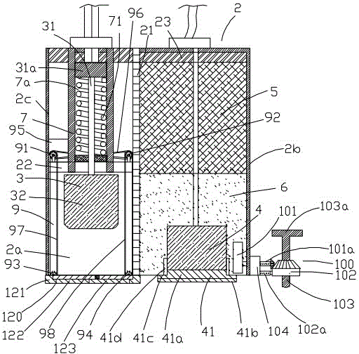
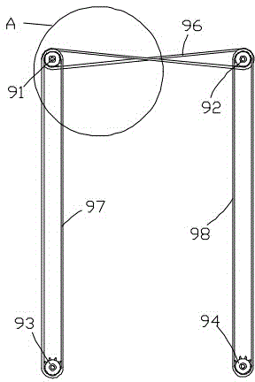
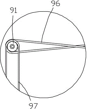
[0032] Figure 1 to Figure 11 Shown is the structural representation of the present invention.

[0033] The reference signs are: data processor 1, controller 11, stress wave generating and receiving device 2, left cavity 2a, right cavity 2b, housing 2c, isolation layer 21, bracket 22, adhesive layer 23, hammer 3. Hammer handle 31, rubber body 31a, hammer head 32, stress wave receiving probe 4, pressure isolation block 41, pressure isolation hard layer 41a, adhesive glue layer 41b, sealing shoulder 41c, sealing ring 41d, counterweight Block 5, damping layer 6, pushing chamber 7, pushing chamber 7a, spring 71, suction and injection device 8, high-pressure gas injection machine 81, air pump 82, opening and closing device 9, left upper transmission wheel 91, right upper transmission wheel 92, lower left transmission wheel 93, lower right transmis...


PUM


Abstract

The invention discloses a low-strain dynamic monitoring device for an underwater pile foundation. A driving hammer and a stress wave receiving probe are arranged in a stress wave generating and receiving device together, the driving hammer can be released and retracted automatically, the stress wave generating and receiving device is fixed to the top of the pile foundation through the combination of a balance weight and a fixing device, an attaching colloidal matter layer is arranged at the lower end of the stress wave receiving probe, an openable water resistant door is arranged on the lower portion of a left cavity, rubber is arranged on the lower surface of the water resistant door, and when a pile is pressed by the stress wave generating and receiving device, a frame block presses the pile to achieve sealing together with a pile cap and then the water resistant door is opened. In this way, the left cavity contains no water all the time, and knocking effect can not be affected by friction between the driving hammer and water when the driving hammer falls down. A length adjuster is arranged to adjust the stretching length of the fixing device so that the low-strain dynamic monitoring device can be adapted to underwater pile foundations with different pile diameters.

Description

technical field [0001] The invention relates to the technical field of pile foundation detection, in particular to a pile foundation detection device in a high water pressure environment, specifically, an underwater pile foundation low-strain dynamic detector. Background technique [0002] Large-diameter cast-in-situ piles are widely used because of their high bearing capacity and low construction noise. They are usually excavated manually or drilled into holes and poured into piles underground or underwater. The quality is affected by the construction process, especially the concrete pouring. It is difficult to control due to the influence of various factors such as working procedures, so the quality problems of pile foundations generally exist, such as too thick sediment, uneven pile body (local mud, segregation, honeycomb, etc.). Therefore, before proceeding to the next process, the quality and integrity of the concrete body of the pile must be inspected and evaluated, es...

Claims


Application Information

Patent Timeline
Patent Type & Authority Applications(China)
IPC IPC(8): E02D33/00
CPCE02D33/00
Inventor 张哲伟李飞波
Owner 高聪聪
Why Eureka
Try Eureka