Camera module

A technology for camera modules and holding components, which is applied to cameras, camera bodies, TVs, etc., can solve the problem of difficult foreign matter intrusion, and achieve the best effect of electromagnetic characteristics

Active Publication Date: 2015-05-13
LG INNOTEK CO LTD
View PDF8 Cites 11 Cited by
  • Summary
  • Abstract
  • Description
  • Claims
  • Application Information

AI Technical Summary

Problems solved by technology

However, due to the structural configuration of the camera module, it is difficult to completely prevent the intrusion of foreign matter, and it is almost impossible to fundamentally prevent internal foreign matter generated during the execution of the autofocus function from moving toward the IR cut filter, and countermeasures are urgently needed

Method used


Image

  • Camera module
  • Camera module
  • Camera module

Examples


Embodiment Construction

[0037] Various example embodiments will be described more fully hereinafter with reference to the accompanying drawings in which some example embodiments are shown. However, inventive concepts may be embodied in many different forms and should not be construed as limited to the exemplary embodiments set forth herein. Rather, these exemplary embodiments are provided so that this description will be thorough and complete, and will fully convey the scope of the inventive concept to those skilled in the art.

[0038] Hereinafter, a camera module according to an exemplary embodiment of the present disclosure will be described in detail with reference to the accompanying drawings.

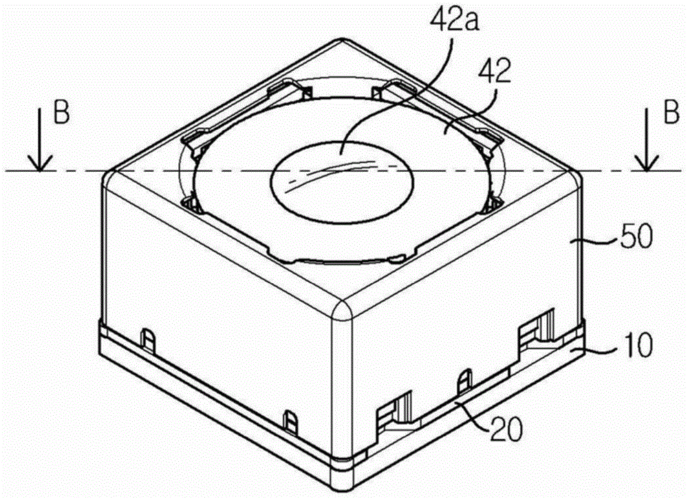
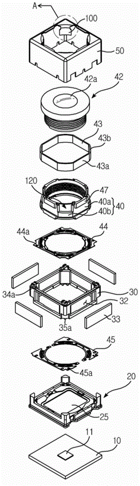
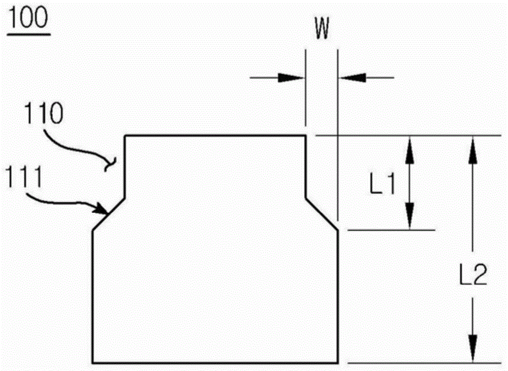
[0039] figure 1 is a perspective view illustrating an example of a camera module according to an exemplary embodiment of the present disclosure; figure 2 for figure 1 The exploded three-dimensional view; image 3 for figure 2 Enlarged view of part 'A' of ; Figure 4 for along figure 1 Sectional ...


PUM


Abstract

A camera module includes a PCB (Printed Circuit Board) mounted with an image sensor, and a holder member arranged at an upper surface of the PCB and mounted with a plurality of magnets. The camera module also includes a bobbin movably mounted from an inner side of the holder member to a direction of an optical axis and installed at a periphery with a coil unit to enable an electromagnetic interaction with the magnets, and a lug protrusively formed from a floor surface of bobbin to a direction of external diameter of bobbin to overlap with the floor surface of the holder member for a predetermined section.

Description

technical field [0001] Teachings according to example embodiments of the present disclosure generally relate to a camera module. Background technique [0002] In general, the camera module may include an optical system formed with an image sensor, a PCB (Printed Circuit Board) mounted with the image sensor configured to transmit electrical signals, an IR (infrared) cut filter configured to cut light in an infrared region, and At least one lens configured to transmit an image to the image sensor. In this case, the optical system may be mounted with an actuator module configured to perform an auto focus function and a hand shake correction function. [0003] Internal foreign matter generated by the movement of the actuator module and external contaminants such as dust generated during the assembly process may enter the camera module. These foreign substances often fall on the upper surface of the IR cut filter, resulting in poor-quality images, and various measures are being...

Claims


Application Information

Patent Timeline
IPC IPC(8): G02B7/09G03B13/36H04N5/225
CPCH04N23/57G03B30/00G03B2205/0069
Inventor 闵相竣俞炫午李成国
Owner LG INNOTEK CO LTD
Why Eureka
Try Eureka