Method for implementing holographic waveguide grating large exit pupil

A holographic waveguide and grating technology, which is applied in the coupling of optical waveguides, light guides, optics, etc., can solve the problems of energy loss and low diffraction efficiency of holographic gratings

Inactive Publication Date: 2015-05-13
佛山市智海星空科技有限公司
View PDF3 Cites 11 Cited by
  • Summary
  • Abstract
  • Description
  • Claims
  • Application Information

AI Technical Summary

Problems solved by technology

For example, the holographic waveguide shows the utilization rate of light energy by the grating in the glasses. Due to the low diffraction efficiency of the holographic grating, the coupling in and out of light waves will be accompanied by energy loss.

Method used


Image

  • Method for implementing holographic waveguide grating large exit pupil
  • Method for implementing holographic waveguide grating large exit pupil
  • Method for implementing holographic waveguide grating large exit pupil

Examples


Embodiment Construction

[0037] The present invention provides a method for realizing a large exit pupil of a holographic waveguide grating. In order to make the purpose, technical solution and effect of the present invention clearer and clearer, the present invention will be further described in detail below with reference to the accompanying drawings and examples. It should be understood that the specific embodiments described here are only used to explain the present invention, not to limit the present invention.

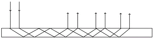
[0038] Such as figure 1 As shown, in order to make the holographic waveguide grating have the property of a large exit pupil, the most important problem is to make the light intensity coupled out by multiple total reflections uniform, so that the diffraction efficiency of each coupling output is different. If the traditional holographic Due to the manufacturing method, it is difficult to realize that the gratings manufactured at the same time have different diffraction efficiencies in di...


PUM


Abstract

The invention discloses a method for implementing holographic waveguide grating large exit pupil. The method is performed through a micro display part, a collimating lens and a holographic waveguide gratin; the interference modulating method is carried out to modulate light waves with different light strength in different areas within the specified plane, and the light waves interferes with another plane beam, the same gating with different diffraction efficiency can be manufactured synchronously, and therefore, the uniform diffraction emission of the light waves can be performed, and as a result, the holographic waveguide grating large exit pupil can be achieved. According to the method, the method of designing a diffraction optical element of any structure is proposed, and the feasibility of the method is verified by experiment; the method is applied to the manufacturing of a holographic gating with different diffraction efficiency in different areas, and therefore, the uniformly-emitted large exit pupil holographic waveguide imaging can be achieved.

Description

technical field [0001] The invention relates to a method for realizing a holographic waveguide grating, in particular to a method for realizing a large exit pupil of the holographic waveguide grating, and belongs to the field of the holographic waveguide grating. Background technique [0002] At the beginning of the 20th century, in order to meet the needs of the air force in combat, an aiming ring with a sight was installed on the aircraft for aiming, similar to the simple aiming system on the early rifles. The three points in a line is the earliest quasi-head-up How the display works. Later, in order to reduce the pilot's aiming burden, other aiming systems were installed on the plane, including the Ortiz sight, which actually installed a handheld monocular on the plane, allowing the pilot to aim and use it. In the early days of World War II, collimation reflective sights and servo halo gyro sights began to appear one after another, mainly composed of ring plate mechanism...

Claims


Application Information

Patent Timeline
Patent Type & Authority Applications(China)
IPC IPC(8): G02B27/44G02B6/34G03H1/02
CPCG02B27/4205G02B6/124G02B27/0189
Inventor 赵晓东
Owner 佛山市智海星空科技有限公司
Why Eureka
Try Eureka