Integrated pressure-resistant shell assembly

A pressure-resistant shell and component technology, which is applied in the field of nuclear reactor control and protection systems, can solve problems such as low economic benefits, leakage, and unfavorable safe operation of the nuclear power industry, and achieve the effect of low economic benefits

Active Publication Date: 2015-05-13
喻杰 +1
View PDF7 Cites 10 Cited by
  • Summary
  • Abstract
  • Description
  • Claims
  • Application Information

AI Technical Summary

Problems solved by technology

[0005] In view of the above-mentioned control rod drive mechanism, the Ω weld seam that exists under the action of stress corrosion during the operation of the reactor leads to leakage, which is not conducive to the safe operation

Method used


Image

  • Integrated pressure-resistant shell assembly
  • Integrated pressure-resistant shell assembly
  • Integrated pressure-resistant shell assembly

Examples


Embodiment 1

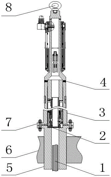
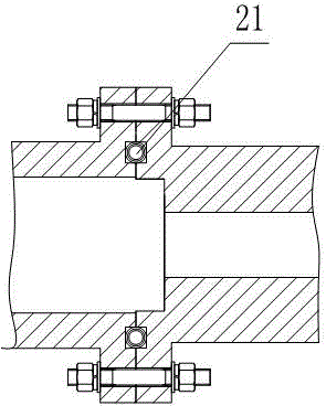
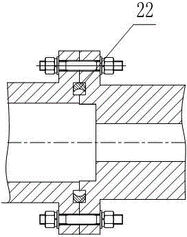
[0032] Such as Figure 1 to Figure 4 As shown, an integrated pressure-resistant shell assembly includes a pressure-resistant shell 3 and a socket 5. The pressure-resistant shell 3 is a columnar structure provided with blind holes along its axial direction. The open end of the pressure-resistant shell 3 and the One end of the pipe seat 5 is fixed with a connecting flange 7, and the two connecting flanges 7 are connected by a plurality of connecting bolts, and there is also a seal between the two connecting flanges 7 for realizing the sealing of the joint of the two connecting flanges 7. Gasket 2, the gasket 2 is a C-shaped elastic sealing ring 21 or an O-shaped elastic sealing ring 22;

[0033] The O-shaped elastic sealing ring 22 is a metal ring with a crescent-shaped cross section;

[0034] The C-shaped elastic sealing ring 21 includes an annular elastic ring 23 and at least one layer of metal wrapping layer 24 wrapped on the elastic ring 23 .

[0035] In this embodiment, t...

Embodiment 2

[0039] The present embodiment is further limited on the basis of embodiment 1, as Figure 1 to Figure 4 As shown, in order to facilitate the processing of the pressure shell 3, as a structural form of the pressure shell 3 that is easy to realize, the pressure shell 3 is a multi-section combined structure, and the sections of the pressure shell 3 are welded by V-shaped Seam 4 connected.

[0040] In order to facilitate the processing of the pressure shell 3, as another easy-to-implement structure form of the pressure shell 3, the pressure shell 3 is an integral forging or an integral structure obtained by drilling.

[0041] In order to facilitate the installation and maintenance of the control rod drive mechanism, the free end of the pressure shell 3 is also provided with lifting lugs 8 .

[0042] As a connecting bolt material with good high temperature strength and excellent thermal relaxation resistance, the material of the connecting bolt is carbon alloy steel.

[0043] In ...

Embodiment 3

[0046] This embodiment is further limited on the basis of any one of the above embodiments, such as Figure 1 to Figure 4 As shown, in order to simplify the structure of the elastic ring 23, facilitate the manufacture of the elastic ring 23, prolong the service life of the O-shaped elastic sealing ring 22, the elastic ring 23 and the metal cladding layer 24 under radiation, and reduce the residual radiation of the control rod drive mechanism during maintenance To the injury of the maintenance personnel, the materials of the O-shaped elastic sealing ring 22, the elastic ring 23 and the metal coating layer 24 are all nickel-based alloys, and the elastic ring 23 is a spring connected end to end.

[0047] In order to facilitate the manufacture of the C-shaped elastic sealing ring 22, the metal wrapping layer 24 is also provided with embedded notches 25 distributed around its circumference. The above structure facilitates inserting the elastic ring 23 from the embedded notch 25 . ...


PUM


Abstract

The invention discloses an integrated pressure-resistant shell assembly. The integrated pressure-resistant shell assembly comprises a pressure-resistant shell and a tube base, wherein the pressure-resistant shell is of a columnar structure with a blind hole in an axial direction, the opening end of the pressure-resistant shell and one end of the tube base are both fixed with connecting flanges, two connecting flanges are connected by a plurality connecting bolts, a sealing gasket for sealing the connecting position of two connecting flanges is arranged between two connecting flanges, the sealing gasket is a C-shaped elastic sealing ring or an O-shaped elastic sealing ring; the O-shaped elastic sealing ring is a metal ring of which the cross section is of a crescent shape, the C-shaped elastic sealing ring comprises a ring-shaped elastic ring and at least one metal wrapping layer wrapped on the elastic ring. The integrated pressure-resistant shell assembly can be used for solving the problems of leakage caused by omega welded corrosion, welding of dissimilar metals, high welding difficulty and low economic benefit, and a problem that the existing pressure-resistant shell assembly is not good for safe operation of the nuclear power industry or use in the improved control rod driving mechanism in the prior art.

Description

technical field [0001] The invention relates to the field of nuclear reactor control and protection systems, in particular to an integrated pressure-resistant shell assembly. Background technique [0002] The reactor control rod drive mechanism is the servo mechanism of the reactor control and protection system. It is the actuator of the reactor control system and protection system. or power off and drop rods to complete the function of adjusting reactor reactivity or accidental safety shutdown; the control rod drive mechanism completes the start-up, power adjustment, maintenance power, The safety and reliability of safety shutdown under shutdown and accident state directly affect the safety and operation of the reactor. [0003] The reactor control rod driving mechanism is composed of six major components: a pressure casing component, a claw component, a driving rod component, a coil component, a rod position detector component, and a heat shield component. Among them...

Claims


Application Information

Patent Timeline
IPC IPC(8): G21C7/14
CPCG21C7/14Y02E30/30
Inventor 喻杰李泽文
Owner 喻杰
Why Eureka
Try Eureka