Boron injection system for second reactor shutdown system of research reactor

A technology of shutdown system and boron injection, which is applied in the field of boron injection system, can solve the problem of unsatisfactory compliance with the principle of diversity, and achieve the effects of easy manufacturing and installation, fast action and simple structure

Active Publication Date: 2015-05-13
CHINA INSTITUTE OF ATOMIC ENERGY
View PDF5 Cites 3 Cited by
  • Summary
  • Abstract
  • Description
  • Claims
  • Application Information

AI Technical Summary

Problems solved by technology

The most commonly used method for the first shutdown system of research reactors is to drop or insert control rods, while for the second shutdown system, except for a few research reactors that can discharge heavy water as a neutron reflection layer

Method used


Image

  • Boron injection system for second reactor shutdown system of research reactor
  • Boron injection system for second reactor shutdown system of research reactor
  • Boron injection system for second reactor shutdown system of research reactor

Examples


Embodiment 1

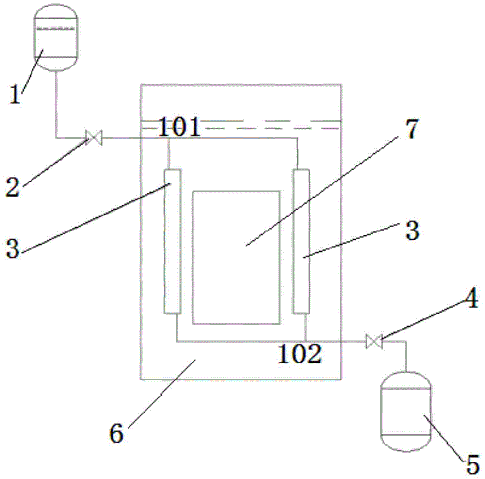
[0018] like figure 1 As shown, it is a schematic structural view of the boron injection system used for the second shutdown system of the research reactor in Embodiment 1 of the present invention. The boron injection system includes a boron liquid tank 1, an inlet valve 2, a boron injection pipe 3, an outlet valve 4 and Boron liquid recovery tank 5. The liquid outlet of the boron liquid tank 1 is connected with the liquid inlet of the boron injection pipe 3 through the first pipeline 101, and the liquid outlet of the boron injection pipe 3 is connected with the boron liquid recovery tank through the second pipeline 102 5, the inlet valve 2 is set on the first pipeline 101, and the outlet valve 4 is set on the second pipeline 102. In this embodiment, the boron injection pipe 3 has at least Two are arranged in parallel around the fuel assembly 7 in the reactor 6 . The boric acid solution meeting the concentration requirements is filled in the boron liquid tank 1 . When there ...

Embodiment 2

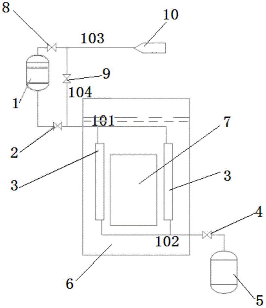
[0020] like figure 2 As shown, it is a schematic structural diagram of the boron injection system used for the second shutdown system of the research reactor in the second embodiment of the present invention. The difference between this embodiment and the first embodiment is that the boron injection system of this embodiment also includes a gas source The device 10 is used to provide pressure difference to the boron injection system. The gas outlet of the gas source device 10 is connected with the boron liquid tank 1 through a third pipeline 103, the first valve 8 is arranged on the third pipeline 103, and the third pipeline 103 and the first pipeline 101 pass through the third pipeline 103. Four pipelines 104 communicate, the second valve 9 is set on the fourth pipeline 104, the connecting end of the fourth pipeline 104 and the third pipeline 103 is located at the intake end of the first valve 8, the fourth The connecting end of the pipeline 104 and the first pipeline 101 i...

Embodiment 3

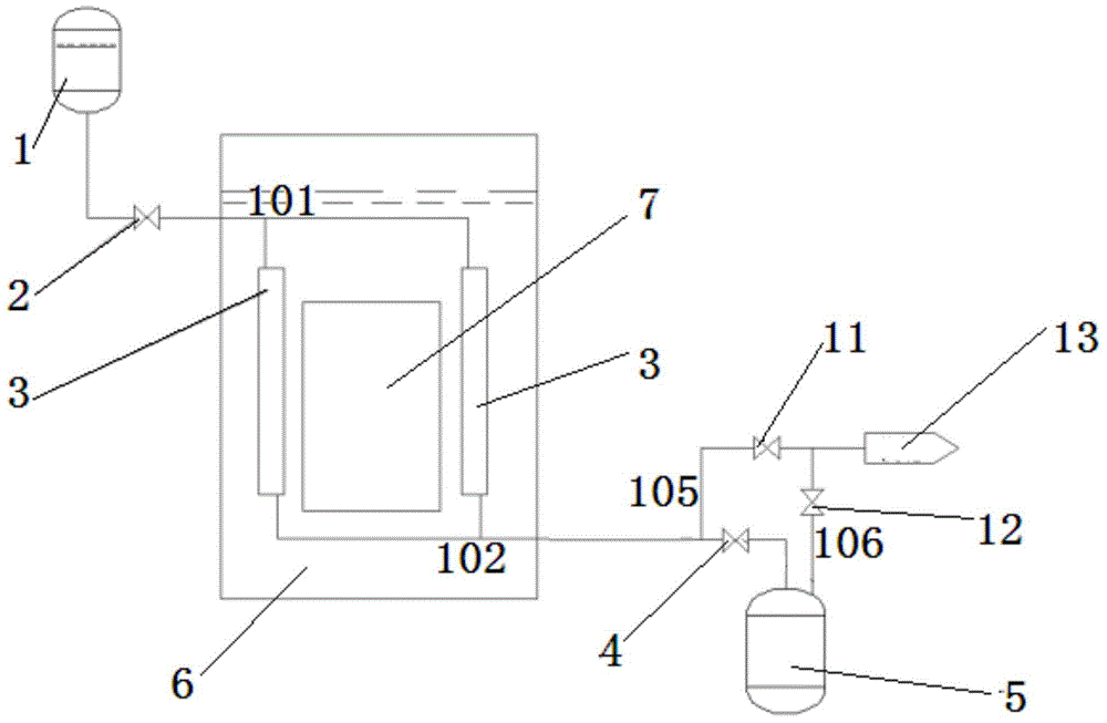
[0023] like image 3 As shown, it is a schematic structural diagram of the boron injection system used for the second shutdown system of the research reactor in the third embodiment of the present invention. The difference between this embodiment and the first embodiment is that the boron injection system of this embodiment also includes vacuum pumping The device 13 is used to provide pressure difference to the boron injection system. The vacuum device 13 is connected with the second pipeline 102 through the fifth pipeline 105, and connected with the boron liquid recovery tank 5 through the sixth pipeline 106, the third valve 11 is set on the fifth pipeline 105, and the sixth The fourth valve 12 is provided on the pipeline 106 , and the connecting end of the fifth pipeline 105 and the second pipeline 102 is located at the liquid inlet end of the outlet valve 4 .

[0024] When situations such as accidents occur and the reactor is to be shut down, the inlet valve 2 is opened. I...


PUM


Abstract

The invention provides a boron injection system for a second reactor shutdown system of a research reactor. The system comprises a boron liquid tank, an inlet valve, a boron injection pipe, an outlet valve and a boron liquid recovery tank, wherein a liquid outlet of the boron liquid tank is connected with a liquid inlet of the boron injection pipe through a first pipeline; a liquid outlet of the boron injection pipe is connected with a liquid inlet of the boron liquid recovery tank through a second pipeline; the inlet valve is arranged on the first pipeline; the outlet valve is arranged on the second pipeline; the boron injection pipe is arranged around a fuel assembly in the reactor. Compared with the prior art, the boron injection system for the second reactor shutdown system of the research reactor, provided by the invention, is simple in structure, quick in motion, easy to manufacture and mount, and convenient to overhaul; furthermore, the boron solution and a reactor coolant are mutually isolated, so that after the reactor shutdown function is executed, the reactor coolant is not required to be processed, and the normal operation of the reactor can be quickly restored.

Description

technical field [0001] The invention relates to the field of nuclear reactors, in particular to a boron injection system used for the second shutdown system of a research reactor. Background technique [0002] It is the most important function to ensure the safety of the reactor that the reactor can be shut down under any working conditions. For this reason, two sets of shutdown systems are usually required. In addition to being independent from each other, these two systems also require a different approach or principle. The maximum degree of difference in order to reduce the probability of common cause failure. The most commonly used method for the first shutdown system of research reactors is to drop or insert control rods, while for the second shutdown system, except for a few research reactors that can discharge heavy water as a neutron reflection layer, most research reactors still use control rods. Rod movement is used as the second shutdown means, so that the two sh...

Claims


Application Information

Patent Timeline
IPC IPC(8): G21C7/22
CPCG21C7/22Y02E30/30
Inventor 柯国土陈会强韩海芬孙征
Owner CHINA INSTITUTE OF ATOMIC ENERGY
Why Eureka
Try Eureka