
Section dimension adjusting device for hooping box of steel reinforcement framework machine

A technology of section size and adjustment device, applied in the field of section size adjustment mechanism of stirrup box of steel frame forming machine, can solve the problems of production process gap and single style of steel frame, and achieve the effect of convenient storage, simple and reasonable structure, and convenient storage.

Inactive Publication Date: 2015-05-20
SHANDONG JIANZHU UNIV
View PDF6 Cites 1 Cited by
  • Summary
  • Abstract
  • Description
  • Claims
  • Application Information

AI Technical Summary

Problems solved by technology

[0002] The forming of the reinforced skeleton adopts a special seam welder to weld multiple round or square main reinforcements and spiral stirrups wound on the main reinforcement. When the reinforced skeleton is formed, a driving system is required to drive the main reinforcement as a whole and the relative traction system of the formed skeleton. Rotate to realize the winding of stirrups on the main reinforcement. This forming method improves the mechanization level of steel skeleton forming to a certain extent, but there is still a gap with the energy-saving and environmental protection production process advocated by the country, and for different specifications of polygonal cross-section steel The skeleton is also difficult to shape with this method
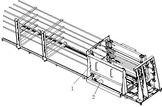
In addition, the manufacturing process of the spiral stirrup on the steel frame directly affects the quality and production efficiency of the steel frame. When the existing steel frame seam welding machine makes the steel frame, it needs to be welded while winding the spiral stirrup. If the spiral stirrup is pre-processed Compression "spring shape" can save the forming time of the steel frame; the existing steel frame seam welding machine has a single style of steel frame, which can only surround the outer circumference of the main bar. If the spiral stirrup is pre-processed into a spiral shape, the stirrup The method of placing the main reinforcement first and then inserting it can produce a steel skeleton with a staggered network structure of spiral stirrups. This new reinforcement skeleton forming method requires special reinforcement skeleton forming equipment. The key part of this equipment is the spiral continuous stirrup pressure storage. And orderly release device - stirrup box

Method used


Image

  • Section dimension adjusting device for hooping box of steel reinforcement framework machine
  • Section dimension adjusting device for hooping box of steel reinforcement framework machine
  • Section dimension adjusting device for hooping box of steel reinforcement framework machine

Examples


Embodiment 1

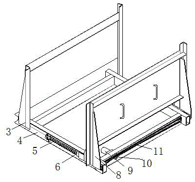
[0021] Embodiment one: if figure 2 As shown, the cross-sectional size adjustment device 2 of the stirrup box of the steel frame machine includes a screw mechanism arranged along the cross-sectional direction of the stirrup box 1 and a chain transmission mechanism for driving the screw mechanism. The two ends of the screw mechanism are fixed on the stirrup box. 1 The amplitude modulation lead screw 5 of the bottom frame 4 and the nut 6 connected to the movable frame of the stirrup box form a spiral pair, and the chain transmission mechanism is installed on the stirrup box 1 bottom frame 4 to drive the amplitude modulation screw 5 to rotate, so that the stirrup box 1 movable frame 8 moves with nut 6. Two groups of amplitude-modulating lead screws 5 of the screw mechanism are symmetrically arranged in parallel with the same thread direction, and are respectively connected with the sprockets of the chain transmission mechanism. Two nuts 6 are arranged at intervals on the same ...

Embodiment 2

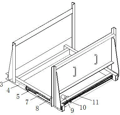
[0022] Embodiment two: if image 3 As shown, the cross-sectional size adjustment device 2 of the stirrup box of the steel frame machine also includes a screw mechanism arranged along the cross-sectional direction of the stirrup box 1 and a chain transmission mechanism for driving the screw mechanism. The two ends of the screw mechanism are fixed on the stirrup The amplitude modulation lead screw 5 of the bottom frame 4 of the box 1 and the nut connected to the movable frame 8 of the stirrup box 1 form a spiral pair, and the chain transmission mechanism is installed on the bottom frame 4 of the stirrup box 1 to drive the amplitude modulation screw 5 to rotate, so that the stirrup box 1 Movable frame 8 moves with nut. Two groups of amplitude-modulating lead screws 5 of the screw mechanism are symmetrically arranged in parallel with the same thread direction, and are respectively connected with the sprockets of the chain transmission mechanism. The difference from Embodiment 1 i...


PUM


Abstract

The invention discloses a section dimension adjusting device for a hooping box of a steel reinforcement framework machine. The section dimension adjusting device for the hooping box of the steel reinforcement framework machine comprises a screw mechanism arranged in the direction of the cross section of the hooping box and a chain driving mechanism used for driving the screw mechanism, in the screw mechanism, a screw pair is composed of amplitude modulation lead screws and a nut set which is connected with a hooping box movable frame, wherein two ends of the amplitude modulation lead screws are fixed to a hooping box underframe; the chain driving mechanism is installed on the hooping box underframe to drive the amplitude modulation lead screws to rotate backwards and to make the hooping box movable frame to move with nuts. Two amplitude modulation lead screws are symmetrically arranged in parallel, the directions of the threads are identical, and the two amplitude modulation lead screws are each connected with chain wheels of the chain driving mechanism. A sliding rail can be arranged on the joint of the nuts of the screw mechanism and the hooping box movable frame, or two nuts are arranged on the same amplitude modulation lead screw at an interval to support the hooping box movable frame and lead the hooping box movable frame to move. By means of the section dimension adjusting device, the breadth of the hooping box, namely the cross section dimension, can be adjusted according to screw constant hooping dimension, and the storage of the hooping is convenient.

Description

technical field [0001] The invention belongs to the technical field of steel bar frame forming construction in the construction industry, and in particular relates to a section size adjustment mechanism of a stirrup box of a steel bar frame forming machine. Background technique [0002] The forming of the reinforced skeleton adopts a special seam welder to weld multiple round or square main reinforcements and spiral stirrups wound on the main reinforcement. When the reinforced skeleton is formed, a driving system is required to drive the main reinforcement as a whole and the relative traction system of the formed skeleton. Rotate to realize the winding of stirrups on the main reinforcement. This forming method improves the mechanization level of steel skeleton forming to a certain extent, but there is still a gap with the energy-saving and environmental protection production process advocated by the country, and for different specifications of polygonal cross-section stee...

Claims


Application Information

Patent Timeline
IPC IPC(8): B21F15/08
Inventor 张明勤马荣全孟宪举苗冬梅原政军姚玉善王晴刘昆王凯靳斐郝圣文张旭
Owner SHANDONG JIANZHU UNIV
Learn More