Non-rigid shaft combined machining device

A combined processing, non-rigid technology, applied in the field of mechanical processing, can solve the problems of high requirements for workpiece processing equipment, undemanding processing accuracy, time-consuming and labor-intensive, etc., to achieve stable surface residual stress and microstructure changes, improve accuracy and production efficiency, The effect of reducing the spread

Inactive Publication Date: 2015-05-20
王树林
View PDF0 Cites 2 Cited by
  • Summary
  • Abstract
  • Description
  • Claims
  • Application Information

AI Technical Summary

Problems solved by technology

When the precision requirements of non-rigid shaft parts are high (IT7-IT8, Ra = 0.32mm), the traditional processing method cannot meet the requirements, the geometric shape deviation of the product is large, the processing accuracy cannot be required, the production efficiency is low, time-consuming and laborious, and The workpiece has high requirements on the processing equipment, which increases the production cost

Method used


Image

  • Non-rigid shaft combined machining device

Examples


Embodiment Construction

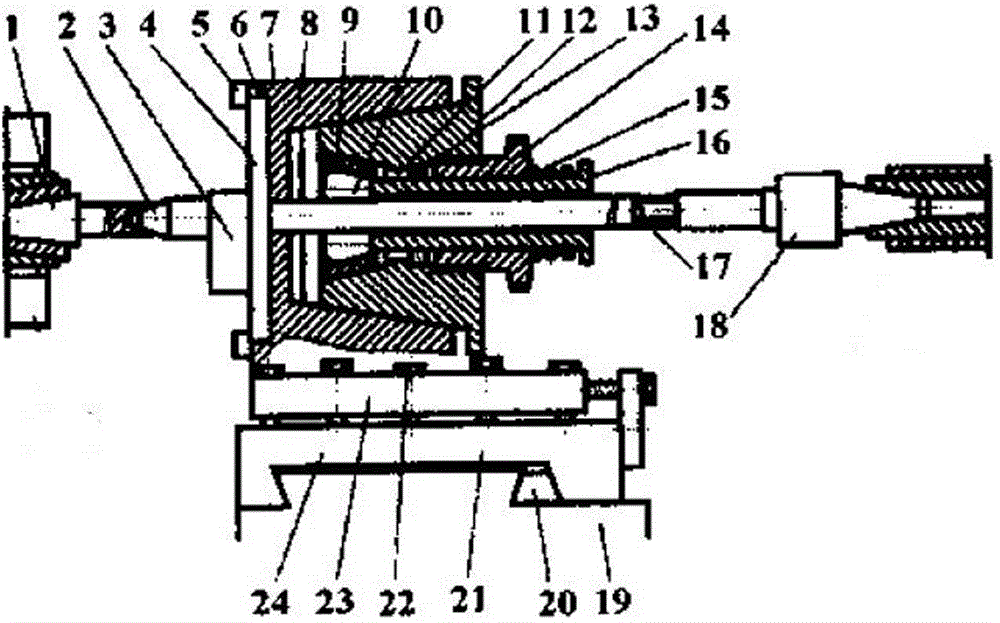
[0010] The non-rigid shaft combination processing device of the present invention includes a base plate 24 fixed on the lathe tool rest 19 through a wedge 20, and a base plate 23 is fixedly connected to the base plate 24 through a fastening screw 22 and an adjustment screw 21. The base plate 23 is connected to There is a processing head 7 and a machine body 8. A top is arranged on the two end faces corresponding to the processing head, which are respectively a front top 1 and a rear top 18. A guide sleeve is arranged on the front top 1 and the rear top 18, respectively. It is the front guide sleeve 2 and the rear guide sleeve 17, one end of the body 8 is provided with a guide rail 6, the guide rail 6 is connected with a knife seat 4 by a compactor 5, and a boss 3 is arranged on the knife seat 4, the The other end of the body 8 is provided with a tapered hole. A deformation device is arranged in the taper hole of the body 8, and the deformation device includes a deformation bod...


PUM


Abstract

The invention relates to the field of machining, in particular to a non-rigid shaft combined machining device. The non-rigid shaft combined machining device comprises a bottom plate which is fixed on a lathe carriage through a wedge, and the bottom plate is fixedly connected with a bottom plate body through a fastening screw and an adjusting screw. The bottom plate body is connected with a machining head and a machine body. The two end faces corresponding to the machining head are each provided with a center, and the centers comprise the front center and the rear center. The front center and the rear center are each provided with a guide sleeve, and the guide sleeves comprise the front guide sleeve and the rear guide sleeve. A guide rail is arranged at one end of the machine body, and the guide rail is connected with a tool apron through a presser. The other end of the machine body 8 is provided with a taper hole. According to the non-rigid shaft combined machining device, the microcosmic uneven degree height can be reduced, the product surfaces can be enhanced, the dispersive range of product dimension and geometrical shape tolerances is reduced, the surface residual stress and microcosmic structure variation is stable, and the machined surface precision and the production efficiency are improved.

Description

technical field [0001] The invention relates to the field of mechanical processing, in particular to a non-rigid shaft combined processing device. Background technique [0002] The non-rigid shaft is a common part in the machine, such as the piston rod of the hydraulic cylinder of the tractor in the agricultural machinery, and the joystick in the textile machinery is one of them. Frames, heel holders, double-wheel knives, etc. When the precision requirements of non-rigid shaft parts are high (IT7-IT8, Ra = 0.32mm), the traditional processing method cannot meet the requirements, the geometric shape deviation of the product is large, the processing accuracy cannot be required, the production efficiency is low, time-consuming and laborious, and The workpiece has high requirements on the processing equipment, which increases the production cost. Contents of the invention [0003] In order to solve the above problems, the present invention provides a method that can reduce th...

Claims


Application Information

Patent Timeline
Patent Type & Authority Applications(China)
IPC IPC(8): B23B25/00B23B23/00
CPCB23B5/08
Inventor 王树林
Owner 王树林
Why Eureka
Try Eureka