Numerical control electric spark deposition knife handle

A technology of EDM deposition and tool holder

Active Publication Date: 2015-05-20
HARBIN INST OF TECH
View PDF13 Cites 17 Cited by
  • Summary
  • Abstract
  • Description
  • Claims
  • Application Information

AI Technical Summary

Problems solved by technology

[0004] The purpose of the present invention is to solve the problem that the existing manual electric spark deposition cannot realize the precise control of the appear

Method used


Image

  • Numerical control electric spark deposition knife handle
  • Numerical control electric spark deposition knife handle
  • Numerical control electric spark deposition knife handle

Examples


specific Embodiment approach 1

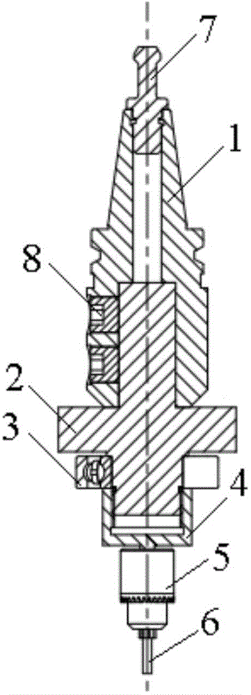
[0024] Specific embodiment 1: This embodiment is a numerically controlled electrical discharge deposition tool holder, including tool holder body 1, insulator 2, bearing 3, sleeve 4, drill chuck 5, electrode 6, pull nail 7 and set screw 8. ;

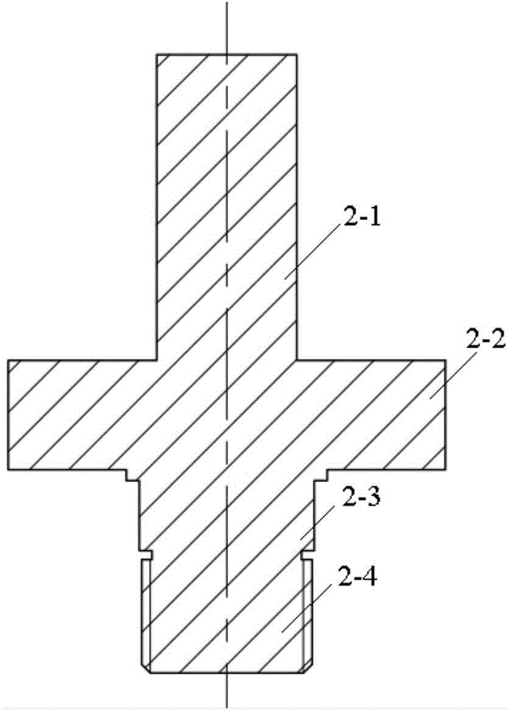
[0025] The insulator 2 includes a handle portion 2-1, a retaining ring 2-2, a bearing mounting portion 2-3 and a threaded portion 2-4;

[0026] The upper end of the shank body 1 is connected with a pull nail 7, and the shank 2-1 is inserted into the lower end of the shank body 1. The shank body 1 is provided with a set screw 8, and the set screw 8 connects the shank body 1 is fixedly connected with the shank 2-1; the inner ring of the bearing 3 is assembled to the bearing installation part 2-3, the threaded part 2-4 is threadedly connected with the sleeve 4, and the bearing 3 is fixed on the sleeve 4 and the retaining ring 2 -2; the lower end of the sleeve 4 is equipped with a drill chuck 5, and the lower end of the drill chuck 5 is equipped...

specific Embodiment approach 2

[0043] The second embodiment: The difference between this embodiment and the first embodiment is that the lower end of the sleeve 4 is connected to the drill chuck 5 through a thread or a taper hole. Others are the same as the first embodiment.

specific Embodiment approach 3

[0044] Embodiment 3: The difference between this embodiment and Embodiment 1 or 2 is that the positive electrode of the power source of the electric spark deposition machine is welded to the outer ring of the bearing, and the negative electrode is connected to the workpiece to be deposited. Others are the same as the first or second embodiment.

[0045] In this embodiment, the positive electrode of the power source of the EDM is welded to the outer ring of the bearing, and the negative electrode is connected to the workpiece. Under the control of the numerical control program, the coating is prepared on the workpiece according to the set deposition track.


PUM


Abstract

The invention provides a numerical control electric spark deposition knife handle, and relates to a knife handle, in particular to the numerical control electric spark deposition knife handle. The numerical control electric spark deposition knife handle aims at solving the problem that an existing manual electric spark deposition is incapable of achieving an accurate control on apparent characteristics, a coating structure and a coating performance of a settled layer. The device comprises a knife handle body, an insulating part, a bearing, a sleeve, a drill chuck and an electrode. The insulating part comprises a handle part, a baffle ring, a bearing installing part and a thread part. The upper end of the knife handle body is connected with a blind rivet. The handle part is arranged inside the lower end of the knife handle body. The knife handle body is provided with set screws. The knife handle body is fixedly connected with the handle part through the set screws. An inner ring of the bearing is arranged on the bearing installing part. The thread part is connected with the sleeve in a threaded mode, and the bearing is fixed between the sleeve and the baffle ring. The lower end of the sleeve is provided with the drill chuck. The lower end of the drill chuck is provided with the electrode. The numerical control electric spark deposition knife handle is achieved.

Description

Technical field [0001] The invention relates to a knife handle, in particular to a numerical control electric spark deposition knife handle. Background technique [0002] At present, manual EDM is used for EDM deposition. Although the operation is simple, it cannot achieve precise control of the apparent characteristics (thickness, roughness), coating structure and coating performance of the deposited layer. The reproducibility of structure and performance is poor. [0003] The use of numerical control electric spark deposition can effectively solve the problems of large manual labor, low efficiency, and poor reproducibility of coating appearance characteristics, structure and performance. Due to the difficulty of connecting the deposition voltage and the CNC milling machine in the integration process of the CNC milling machine and the EDM deposition machine, the numerical control and automation of the EDM deposition process has not been solved. Summary of the invention [0004] T...

Claims


Application Information

Patent Timeline
IPC IPC(8): B23H11/00
CPCC23C24/10
Inventor 何鹏王小荣王朝琴林铁松
Owner HARBIN INST OF TECH
Why Eureka
Try Eureka