Full-automatic electronic printing unit and method
An electronic printing, fully automatic technology, applied in printing devices, printing, typewriters, etc., can solve the problems of complex manufacturing procedures, high environmental pollution, high material and energy consumption, and achieve low material ineffective loss, low environmental requirements, low cost effect
- Summary
- Abstract
- Description
- Claims
- Application Information
AI Technical Summary
Problems solved by technology
Method used
Image
Examples
Embodiment 1
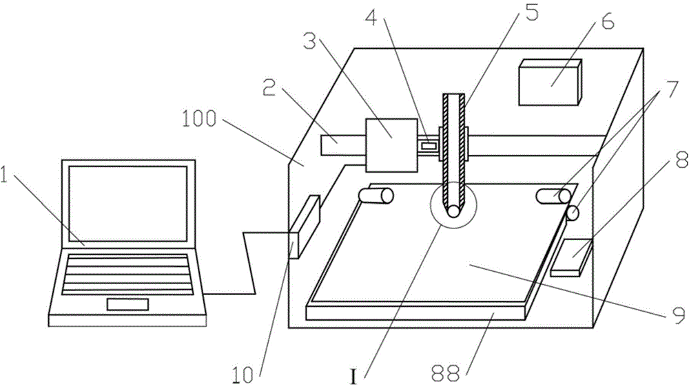
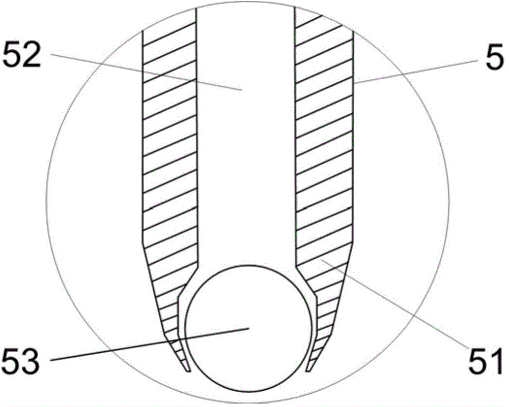
[0058] Such as figure 1 and 2 As shown, the fully automatic electronic printing device of the present invention includes a computer 1, a printing box 100, and the printing box 100 is provided with a paper feeding mechanism, a slide rail 2, a printing mechanism, a temperature control device 6 and a state sensor. The computer 1 is used to generate printing control instructions. Specifically, the computer 1 is installed with a DIY electronic drawing program and a structure database for automatic design of electronic circuits and electronic devices and generation of printing control instructions. Users can design electronic circuit patterns that need to be printed on the computer, and generate structural printing instructions. The paper feeding mechanism is arranged at the bottom of the printing box, which includes a base 88, a conveying unit and a paper feeding control module; the conveying unit is installed on the base, and the conveying unit is used to convey the printing car...
Embodiment 2
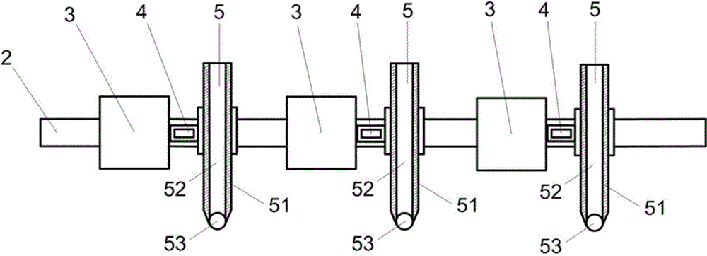
[0075] Figure 4 It is a structural schematic diagram with three ball printing heads in the present invention. This embodiment is different from Embodiment 1 in that it does not need to stop the machine to replace the printing pen to realize multi-attribute electronic printing, and the printing mechanism can not only use one, but can simultaneously provide the printing mechanism of conductive ink and the printing mechanism of P-type semiconductor ink The three printing pens and the corresponding software and hardware control mechanisms can be selected in sequence according to the needs of specific circuits or cooperate with printing at the same time, thereby realizing the production of electronic circuits or devices with specific functions. In addition, two or four printing mechanisms can also be used for printing, and the number of printing mechanisms is determined by the type of the printed product. In this embodiment, the working mode is completely consistent with that of ...
Embodiment 3
[0077] Figure 5 It is a schematic structural diagram of a ball transfer ink type automatic electronic printing device for printing on the surface of a three-dimensional object in the present invention. The difference between this embodiment and Embodiment 1 is that the conveying unit is installed on the base through a three-dimensional moving unit Above, the three-dimensional moving unit drives the three-dimensional movement of the conveying unit and the printing carrier conveyed by the conveying unit along X, Y and Z directions. In this embodiment, the mechanism arm 91 is used as the three-dimensional moving unit. The conveying unit includes a cylinder clamping assembly 12 and a motor 11, the printing carrier is clamped by the cylinder clamping assembly 12, and is arranged on the outer surface of the cylinder clamping assembly, the motor 11 is connected with the cylinder clamping assembly, and Drive cylinder clamping assembly to rotate. During printing, the conveying unit ...
PUM
 Abstract
Description
Claims
Application Information
 - R&D
- Intellectual Property
- Life Sciences
- Materials
- Tech Scout
- Unparalleled Data Quality
- Higher Quality Content
- 60% Fewer Hallucinations
Browse by: Latest US Patents, China's latest patents, Technical Efficacy Thesaurus, Application Domain, Technology Topic, Popular Technical Reports.
© 2025 PatSnap. All rights reserved.Legal|Privacy policy|Modern Slavery Act Transparency Statement|Sitemap|About US| Contact US: help@patsnap.com


