Integrated pouring device for installation of rail column type inspection pit fastening system

A technology for system installation and pit inspection, which is applied in the direction of track, track laying, track maintenance, etc., can solve the problems of low recycling value, small column size, time-consuming and material-consuming, reduce labor and cooperation between processes, overcome The formwork efficiency is slow and the effect of saving labor costs

Inactive Publication Date: 2015-05-20
邵冠慧
View PDF5 Cites 10 Cited by
  • Summary
  • Abstract
  • Description
  • Claims
  • Application Information

AI Technical Summary

Problems solved by technology

[0009] 1. It is necessary to protect the fastener system, and it is time-consuming to bring plastic bags to the fasteners, and it is easy to damage the plastic bags, pollute the fasteners, and jam the bolts when the concrete is poured or vibrated;
[0010] 2. The area under the rubber pad (wooden board) is prone to vibration leakage due to the large turning radius of the vibrating rod. First, there are many floating paddles and low strength. Second, the surface is uneven. After the wooden board is removed and the rubber pad is replaced , there is a gap between the bottom layers of the rubber pad on the concrete finish surface, which affects the force transmission;
[0011] 3. Wooden formwork processing requires special cutting equipment, professional woodworkers, and auxiliary materials such as square wood when setting up the formwork, which is time-consuming and time-consuming;
[0012] 4. The size of the column is small, so the wooden formwork used for assembly is generally cut to a smaller size, and the recycling value is low. Generally, construction units incinerate more, which is not environmentally friendly

Method used


Image

  • Integrated pouring device for installation of rail column type inspection pit fastening system
  • Integrated pouring device for installation of rail column type inspection pit fastening system
  • Integrated pouring device for installation of rail column type inspection pit fastening system

Examples


Embodiment 1

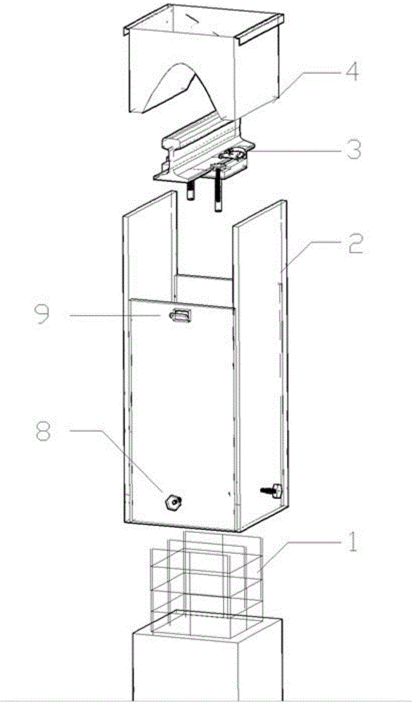
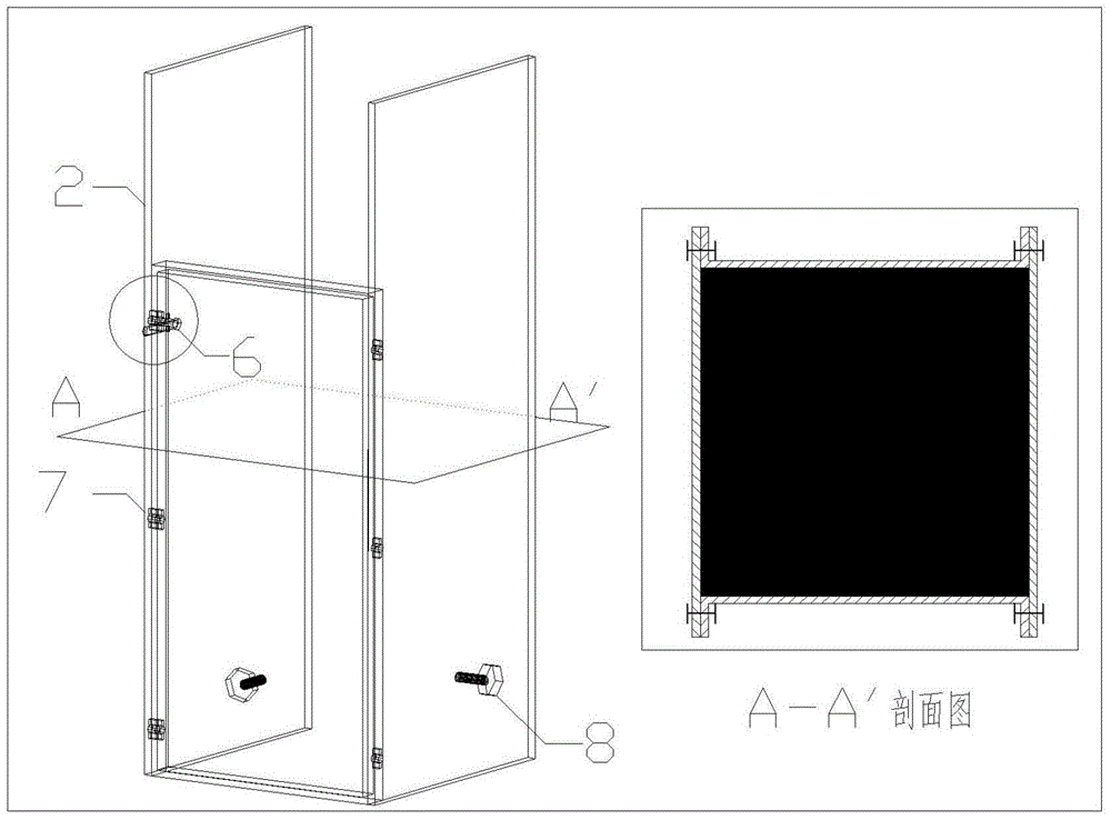
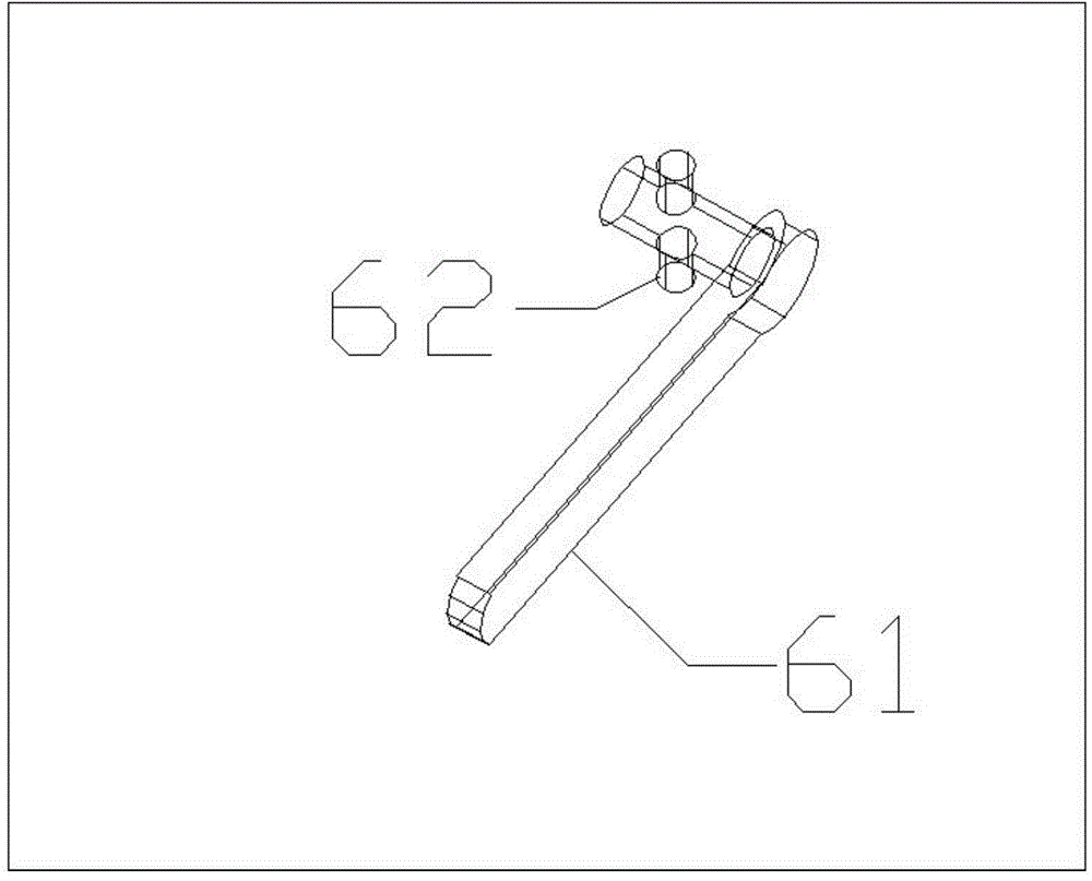
[0035] Such as Figure 1~4 As shown, an integrated pouring device for the installation of rail column-type inspection pit fastener system, the reserved steel bar 1 of the column is covered by a shaped aluminum formwork 2, and two pieces of steel rail 3 parallel to the reserved steel bar 1 The height of the shaped aluminum formwork 2 is higher than the other two shaped aluminum formworks 2 perpendicular to the rail 3, and is used to fix the matching pouring funnel 4. The bottom of the pouring funnel 4 is a parabolic bottom surface with two lower openings, and the bottom The height is flush with the bottom end of the rubber pad 5, and the two lower openings are located on both sides of the steel rail 3; the two adjacent shaped aluminum templates 2 are fixed by the connecting pin 6, and the connecting pin 6 is cross-shaped and includes a rotating head 61 and A group of protrusions 62 perpendicular to the rotor, after the connecting pin 6 passes through the reserved rectangular ba...

Embodiment 2

[0037] A method for laying an integrated pouring device for the installation of rail post-type inspection pit fastener systems, comprising the following steps: firstly erecting steel rails and assembling rail rows, placing iron backing plates, rubber pads under rails or planks and fasteners , anchor bolts, and pre-embedded casings are assembled on the rail; secondly, adjust the line status and fine-tune to the design elevation; then cover the column with the reserved steel bars from all sides with the shaped aluminum formwork, and the height of the shaped aluminum formwork on both sides of the rail It is greater than the height of the rail, and after fixing two adjacent shaped aluminum formworks with connecting pins, the combined aluminum formwork is clamped to the concrete column through the fasteners at the lower part of the formwork, and the pouring funnel is hung on the raised shaped aluminum formwork on both sides to pour. Pour concrete into the bottom surface of the rubbe...


PUM


Abstract

The invention discloses an integrated pouring device for installation of a rail column type inspection pit fastening system. The periphery of a stand column reserved steel bar is wrapped by shaping aluminum formworks, wherein the two shaping aluminum formworks parallel to a steel rail above the reserved steel bar are higher than the other two shaping aluminum formworks at the positions perpendicular to the steel rail, and the shaping aluminum formworks are used for fixing a matched pouring funnel. The invention further discloses a laying method of the integrated pouring device. The integrated pouring device replaces traditional woodworking operation wasting time and materials, solves the problems that the formwork supporting effect is slow and parts are prone to contamination in the pouring process, and is short in construction period, low in use cost, convenient to construct, high in efficiency, good in stability and wide in application range.

Description

technical field [0001] The invention belongs to the technical field of building construction, and in particular relates to an integrated pouring device for the installation of a column-type inspection pit fastener system in a professional track section. Background technique [0002] At present, the construction interface of conventional civil engineering and track professional is generally 50cm below the rail surface of the inspection pit. The reinforced concrete works below the interface shall be constructed by the civil engineering unit and the steel bars shall be reserved. Professionally done. The installation technical process steps of the existing column inspection pit fastener system in the railway or subway section are generally as follows: [0003] 1. First, the erection of the rail and the assembly of the rail row; [0004] 2. According to the requirements of the track laying drawings, assemble the iron backing plate, the rubber pad under the rail and the fastener...

Claims


Application Information

Patent Timeline
Patent Type & Authority Applications(China)
IPC IPC(8): E01B29/00E04H5/06
CPCE01B29/00E04H5/06
Inventor 邵冠慧梁恒辉袁宽瑶靳永福曹福全施正城莫振泽
Owner 邵冠慧
Why Eureka
Try Eureka