
Construction method of water-stop curtain for deep foundation pit by using high-pressure rotary grouting pile machine

A technology of high-pressure rotary jetting pile machine and water-stop curtain, which is applied in basic structure engineering, sheet pile wall, construction, etc., can solve the problem of increasing the income of construction site personnel, materials, machinery and materials, and increasing the construction period of deep foundation pit water-stop curtain , the increase of construction costs and other problems, to achieve the effect of optimizing construction technical parameters, shortening construction period and improving construction quality

Active Publication Date: 2016-07-20
CHINA RAILWAY NO 2 ENG GRP CO LTD +1
View PDF4 Cites 1 Cited by
  • Summary
  • Abstract
  • Description
  • Claims
  • Application Information

AI Technical Summary

Problems solved by technology

When the geological conditions are complicated, especially when a large number of boulders are mixed in the pebble layer, it is very difficult to form holes when passing through the pebble layer, and the construction speed is slow, which will increase the construction period of the deep foundation pit water-stop curtain, thereby increasing the construction site personnel, Income from materials, machinery and materials leads to an increase in construction costs

Method used


Image

  • Construction method of water-stop curtain for deep foundation pit by using high-pressure rotary grouting pile machine
  • Construction method of water-stop curtain for deep foundation pit by using high-pressure rotary grouting pile machine

Examples


Embodiment 1

[0037] Use the following methods to construct the water-stop curtain for the above-mentioned deep foundation pit:

[0038] (1) Modification of high-pressure rotary grouting pile machine

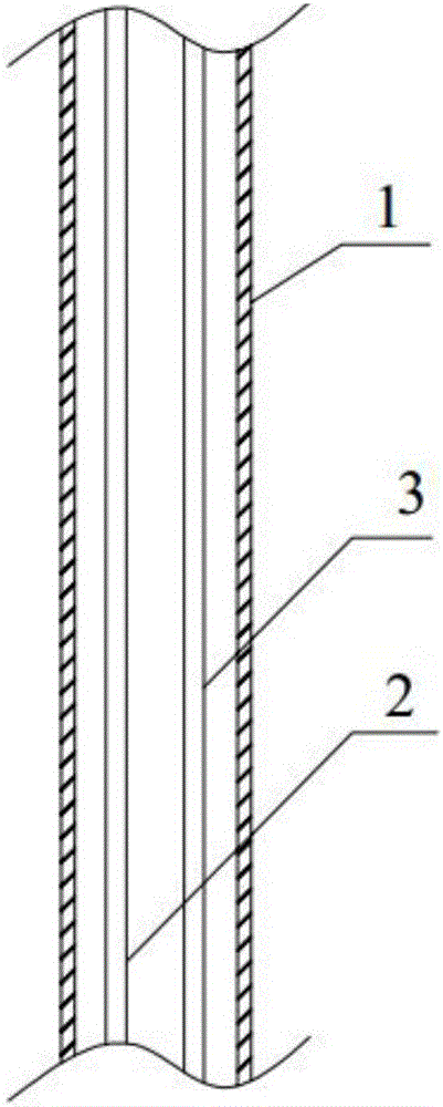
[0039] The CFG pile driver is refitted into a high-pressure rotary grouting pile driver. The modification method is to install the grouting pipe and the gas injection pipe inside the drill pipe of the CFG pile driver. The specific installation method is to remove the drill pipe of the CFG pile driver in sections; The tops of the grouting pipe and the air injection pipe are respectively connected with the high-pressure mud pump and the air compressor, and then the grouting pipe and the air injection pipe are passed through each section of the drill pipe in turn, and the grouting pipe and the air injection pipe are passed through each section of the drill pipe at the same time. The gas injection pipe is fixed and welded at the end of each section of drill pipe with steel hoops. Using the above...

Embodiment 2

[0053] Use the following methods to construct the water-stop curtain for the above-mentioned deep foundation pit:

[0054] (1) Modification of high-pressure rotary grouting pile machine

[0055] The CFG pile driver is refitted into a high-pressure rotary grouting pile driver. The modification method is to install the grouting pipe and the gas injection pipe inside the drill pipe of the CFG pile driver. The specific installation method is to remove the drill pipe of the CFG pile driver in sections; The tops of the grouting pipe and the air injection pipe are respectively connected with the high-pressure mud pump and the air compressor, and then the grouting pipe and the air injection pipe are passed through each section of the drill pipe in turn, and the grouting pipe and the air injection pipe are passed through each section of the drill pipe at the same time. The gas injection pipe is fixed and welded at the end of each section of drill pipe with steel hoops. Using the above...


PUM


Abstract

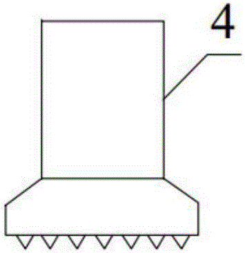
The invention discloses a method for constructing a water-stop curtain for a deep foundation pit by using a high-pressure rotary grouting pile machine. The method of the present invention aims at silt, cohesive soil, loess, sandy soil, artificial filling, pebble layer, mudstone layer and other geological layers that are difficult to form holes, by installing the grouting pipe and gas injection pipe on the CFG pile driver drill Inside, the drill bit of the CFG pile driver is converted into a down-the-hole hammer drill bit, and the construction technology of directly spraying grout into piles after hole formation is adopted.

Description

Technical field [0001] The present invention belongs to the construction field of deep -founded pits, and it specially involves a method of using a high -pressure rotary spray pile driver for the construction of deep -founded pits. Background technique [0002] The curtain of the deep -founded pits is used as a supporting structure of reinforced concrete piles. It uses a high -pressure rotor spray grouting method to solid the soil between the piles and connects the concrete drainage pile to form a closed interception barrier.At present, in the construction method of the traditional deep -founded pit stop water, the construction of a spin -spray pile machine is used. It is necessary to lead the hole first, and then become a pile. After using the drilling of the drilling machine to drill into the design depth,Under the action of the high pressure of the pump, a certain water -asx ratio of cement slurry is pumped to the drill through the high pressure tube, so that the injected high...

Claims


Application Information

Patent Timeline
Patent Type & Authority Patents(China)
IPC IPC(8): E02D19/18E02D5/46
CPCE02D5/18E02D5/46
Inventor 谢卜均柳树沈世强王辉丁建华
Owner CHINA RAILWAY NO 2 ENG GRP CO LTD
Learn More