

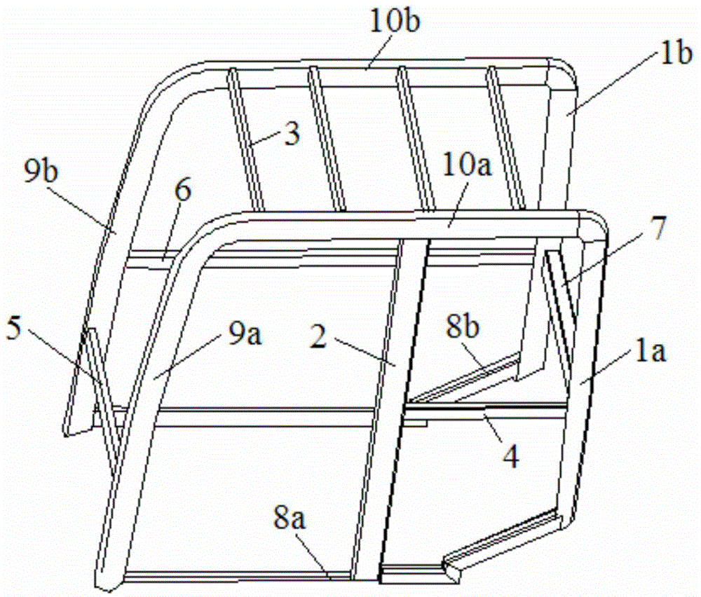
Engineering machine cab body framework, manufacturing method, cab and engineering machine
A construction machinery and cab technology, applied in the cab field, can solve the problems of increased manufacturing cost and processing difficulty, heavy weight, increased design cost and product cycle, and achieve reliable performance, substantial performance improvement, and strong working conditions adaptive effect
- Summary
- Abstract
- Description
- Claims
- Application Information
AI Technical Summary
Problems solved by technology
Method used
Image

Examples
Embodiment Construction
[0055] The specific embodiments of the present invention will be described in detail below in conjunction with the accompanying drawings. It should be understood that the specific embodiments described here are only used to illustrate and explain the present invention, and the protection scope of the present invention is not limited to the following specific embodiments. .
[0056] In order to enable those skilled in the art to have a deeper understanding of the unique technical concept of the present invention, the specific implementation and preferred implementation of the method for manufacturing the main frame of the engineering machinery cab of the present invention will be described below, and the description will be appropriately explained in the course of the description. Some of the creative labor and analysis that goes into the R&D process. On this basis, the specific and preferred embodiments of the construction machine, construction machine cab and main frame there...
PUM
 Abstract
Description
Claims
Application Information