High-efficiency low-noise axial flow fan

An axial flow fan, high-efficiency technology, used in mechanical equipment, machines/engines, liquid fuel engines, etc., can solve the problems of large eddy current loss, large airflow resistance, unsmooth airflow, etc., to improve appearance, reduce noise, Noise reduction effect

Inactive Publication Date: 2015-05-20
PINGAN ELECTRICAL
View PDF7 Cites 5 Cited by
  • Summary
  • Abstract
  • Description
  • Claims
  • Application Information

AI Technical Summary

Problems solved by technology

[0004] 2. Low efficiency
Due to the difference between the diameter of the motor shell and the impeller hub, the motor shell is shorter than the length of the fan shell, so the air flow in the flow channel is not smooth and the eddy current loss is large
Second, in order to form the same annular flow channel as the main engine, both the front muffler and the rear muffler diffuser are designed with inner cylinders. However, the inner cylinders are all straight cylinder structures, and the area of ​​the annular flow channel along the entire length of the front muffler is the same. , the airflow resistance is also greater
[0006] In addition, the current collector and the front muffler are manufactured separately, and then assembled, the processing technology is complicated

Method used


Image

  • High-efficiency low-noise axial flow fan
  • High-efficiency low-noise axial flow fan
  • High-efficiency low-noise axial flow fan

Examples


Embodiment 1

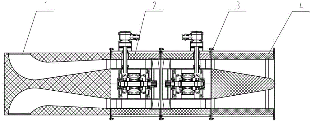
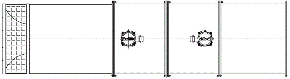
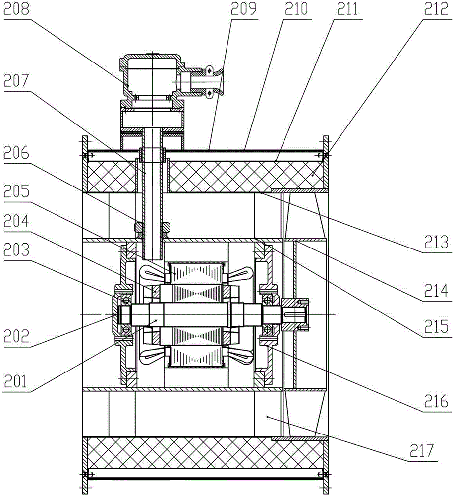
[0039] Example 1, such as figure 1, the present invention includes a main engine 2 and a radial annular air inlet and outlet muffler 1 and a muffler diffuser tube 4 respectively connected at both ends. The main engine 2 includes a shell 209 with a sound-absorbing structure, which forms an air passage with the motor shell 215 . The inner wall of the motor housing 215 is provided with ribs or sectors to support the stator 205. By adjusting the height of the built-in ribs or sectors to match the diameter of the stator, the outer surface of the motor housing 215 is ensured. The diameter is consistent with the diameter of the hub of the impeller 216 and the diameter of the inner cylinder of the front and rear mufflers. One end of the motor casing 215 is basically flush with the end of the main engine casing. After the other side is connected to the impeller, the width of the hub is also the same as the end of the main engine casing At the same time, arrange the flange and the end ...

Embodiment 2

[0045] Example 2, Figure 10 to Figure 13 , which embodies the different internal structures of the radial annular inlet (outlet) wind muffler. According to the principle of radial annular inlet (outlet) wind muffler, the inside of the flow channel is designed as more than one bend, and the noise goes outward along the flow channel. When propagating, there are multiple "barriers" to block, and the noise reduction effect is better; the radial annular inlet (outlet) can be set in the radial direction or axial direction, but the air inlet (outlet) channel has a tapered (expanded) area. The geometric shape is a structural feature that transitions from a radial ring to an axial direction. It is also possible to add a ring-shaped noise reduction structure on the outside of the radial ring-shaped inlet (outlet) to relatively close the flow channel, so that the airflow noise can be blocked by the ring-shaped noise reduction tube once more, and then enter (out) in the axial direction. ...


PUM


Abstract

A high-efficiency low-noise axial flow fan mainly solves the technical problems that an existing axial flow fan is low in efficiency, high in noise and the like. According to the technical scheme, the high-efficiency low-noise axial flow fan is characterized by comprising a main fan body (2), a radial annular inlet (outlet) air muffler device (1) and a muffling diffusion cylinder (4), wherein the two ends of the main fan body (2) are connected with the radial annular inlet (outlet) air muffler device (1) and the muffling diffusion cylinder (4) respectively. A cylindrical housing (209) of the main fan body (2) and a motor housing (215) form an airflow passage. The inner wall of the motor shell (215) is provided with an axial rib plate or a fan-shaped block to support a stator (205). The outer diameter of the motor housing (215) is consistent with the diameter of a hub of an impeller (216), the diameter of an inner cylinder of a front muffler and the diameter of an inner cylinder of a rear muffler. The two ends of the motor housing (215) are basically flush with one end of a main fan body housing. A flange fixing a rotator and an end cover are arranged on the inner side of the motor housing (215). Accordingly, resistance loss is reduced. An air inlet (outlet) flow passage is designed to be of a gradual-shrinkage structure and a gradual-expansion structure, so aerodynamic performance and efficiency are improved; by the adoption of the radial annular inlet (outlet) air muffler device and the main fan body housing muffling structure combining multiple mechanisms, the purpose of noise reduction is achieved. The high-efficiency low-noise axial flow fan can be widely applied to ventilation on various occasions such as mines, tunnels, industries and enterprises.

Description

technical field [0001] The invention relates to a high-efficiency and low-noise axial flow fan. Background technique [0002] Axial flow fans have the characteristics of large flow, small volume and low pressure head, and are widely used in various ventilation systems that require large flow. The simplest structure is to arrange a motor in the middle of a garden cylinder with a flange, and install an impeller on the shaft extension of the motor to form an axial flow fan main body. In order to reduce the noise of the axial flow fan and improve the efficiency, the sound-absorbing material is usually wrapped around the outer periphery of the main engine cylinder to form a sound-absorbing structure. A front muffler with an inner cylinder is connected to the air inlet direction in front of the main engine, and the air inlet is connected to the front muffler. current collector. A muffler diffuser is connected behind the host, and the airflow enters (or exits) the host in the axi...

Claims


Application Information

Patent Timeline
Patent Type & Authority Applications(China)
IPC IPC(8): F04D29/52F04D29/66F04D25/08
CPCF04D29/663F04D29/522F04D29/664
Inventor 陈重新谢星明刘刚王海桥
Owner PINGAN ELECTRICAL
Why Eureka
Try Eureka