Particle damper with ferromagnetic end cap coupled to electromagnetic field at one end and its vibration reduction method for vibrating structures
A particle damper and electromagnetic field technology, applied in the direction of friction shock absorber, non-rotational vibration suppression, magnetic spring, etc., can solve the problems that particle damping is difficult to apply, fixed turbulence is difficult to achieve, and turbulence cannot be achieved. Vibration effect, good vibration reduction effect, effect of increasing energy consumption
- Summary
- Abstract
- Description
- Claims
- Application Information
AI Technical Summary
Problems solved by technology
Method used
Image

Examples
Embodiment 1
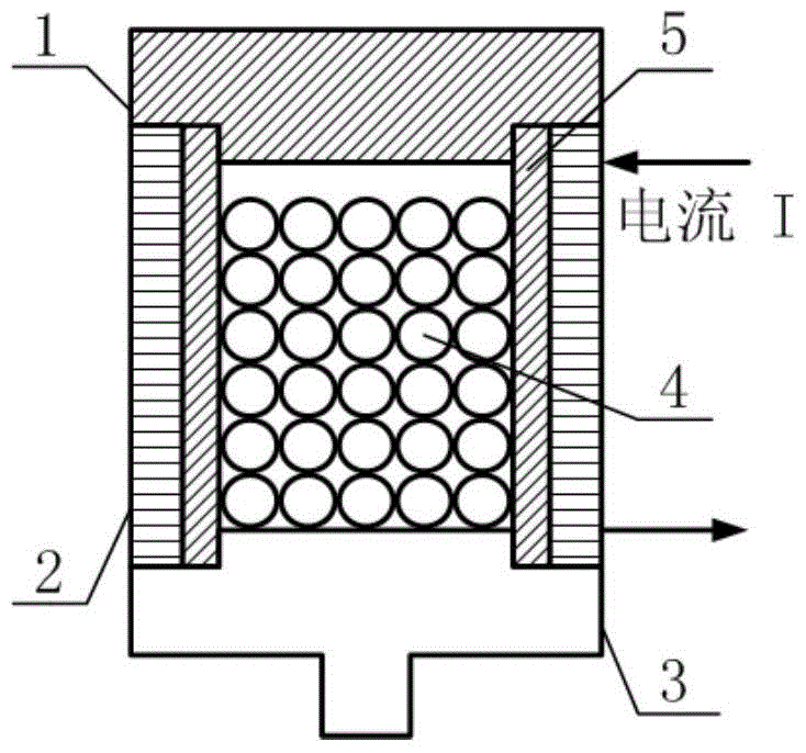
[0032] The structure of the particle damper with a ferromagnetic end cap coupled to the electromagnetic field at one end is as follows: figure 2 As shown, ferromagnetic particles 4 are placed in the non-ferromagnetic cavity 5, and the non-ferromagnetic cavity 5 is sealed by the non-ferromagnetic end cover 1 and the ferromagnetic end cover 3 to form a particle damper. And the densely wound coil 2 is wound outside the non-ferromagnetic cavity 5, and the densely wound coil 2 is wound on the non-ferromagnetic cavity 5 to form a solenoid, wherein the material of the non-ferromagnetic cavity 5 is plexiglass .
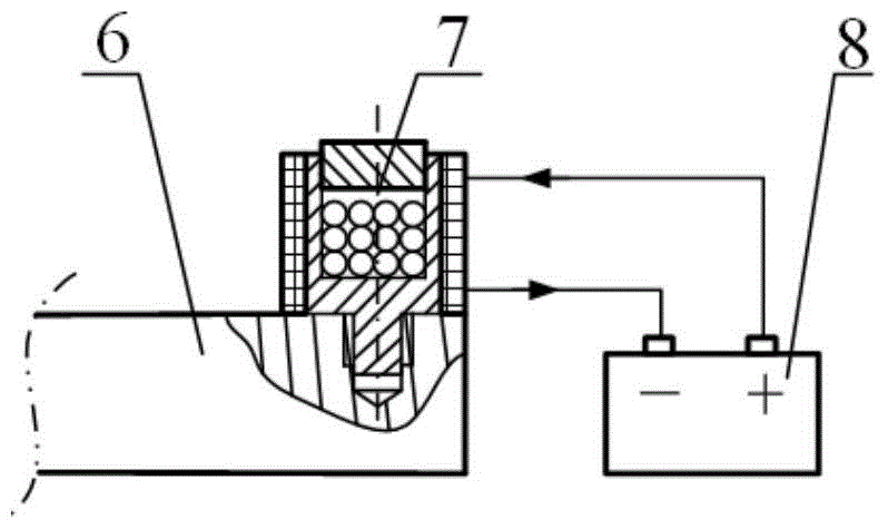
[0033] see image 3 , connect the particle damper 7 with a ferromagnetic end cap coupled to the electromagnetic field at one end to the vibrating structure 6 through threads, supply power to the solenoid through a power supply 8, and generate a magnetic field in the non-ferromagnetic cavity 5. At this time, the ferromagnetic Both the end cap and the ferromagnetic particles...
Embodiment 2
[0038] The structure of the particle damper with a ferromagnetic end cap coupled to the electromagnetic field at one end is as follows: figure 2 As shown, ferromagnetic particles 4 are placed in the non-ferromagnetic cavity 5, and the non-ferromagnetic cavity 5 is sealed by the non-ferromagnetic end cover 1 and the ferromagnetic end cover 3 to form a particle damper. A coil 2 is wound outside the non-ferromagnetic cavity 5, the coil 2 is wound on the non-ferromagnetic cavity 5 to form a solenoid, and the material of the non-ferromagnetic cavity 5 is plexiglass.
[0039] For particle damping under rotating conditions, due to the action of centrifugal force, the particles are tightly compacted together, and the relative motion between particles is sharply reduced, which leads to the deterioration of particle damping and vibration reduction effect. By adjusting the position of the ferromagnetic end cap, the direction of the overall unidirectional force exerted on the particles b...
PUM
 Abstract
Description
Claims
Application Information