Testing device for testing deflagration to detonation transition performance of propellant powder

A technology of combustion-to-detonation and test device, which is used in the test of ammunition, ammunition, weapon accessories, etc., and can solve the problems of incompetent launch environment, prone to false triggering, and large result error.

Inactive Publication Date: 2015-05-20
XIAN MODERN CHEM RES INST
View PDF3 Cites 12 Cited by
  • Summary
  • Abstract
  • Description
  • Claims
  • Application Information

AI Technical Summary

Problems solved by technology

However, the device has the following shortcomings: First, the wavefront-time relationship of propellant and explosive combustion and detonation is characterized by the position-time relationship of the recorded pressure waveform, and the position-time relationship of the pressure waveform is recorded by the ionization probe method. When the time relationship is used, the data acquisition rate of the ionization probe is not high, and false triggering is prone to occur, resulting in a large error in the test results. Therefore, the obtained wavefront-time relationship results of propellant combustion and detonation have large errors
Secondly, when the propellant burns in the gun barrel, one end is a closed barrel and the other end is a movable projectile. The projectile is constantly moving during the reaction process of the propellant, and the two ends of the test tube of the device are closed structures. There are certain differences with the actual launch tube, and cannot be equivalent to the actual launch environment

Method used


Image

  • Testing device for testing deflagration to detonation transition performance of propellant powder
  • Testing device for testing deflagration to detonation transition performance of propellant powder
  • Testing device for testing deflagration to detonation transition performance of propellant powder

Examples


Embodiment Construction

[0016] Combine below Attached picture The present invention is described in further detail with the embodiment, it should be noted that the present invention is not limited to the following specific examples, and all equivalent transformations carried out on the basis of the technical solution of the present invention are all within the protection scope of the present invention.

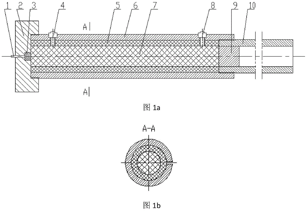
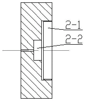
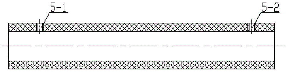
[0017] like figure 1 - Figure 5 As shown, the present embodiment provides a test device for measuring the combustion-to-detonation performance of propellants, including an electric ignition head 1, an end cover 2, an ignition powder 3, a starting point pressure sensor 4, a combustion-to-detonation tube 5, The propellant charge 7 and the terminal pressure sensor 8 are characterized in that they also include a sleeve 6, a simulated bomb 9 and a simulated launch tube 10, wherein the end cover 2 is made of steel with a center step through hole 2-2 in the axial direction. Cylinder, central step th...


PUM


Abstract

The invention discloses a testing device for testing the deflagration to detonation transition performance of propellant powder. The testing device comprises an electric igniter, an end cover, ignition powder, a pressure sensor, a deflagration to detonation transition pipe and charged propellant powder, and further comprises a sleeve, a simulated bullet and a simulated launching pipe. The end cover is a cylinder with a center step through hole in the axial direction, and is connected with the sleeve through threads, the igniter and the ignition powder are arranged in the center through hole of the end cover, the sleeve is a cylinder with an observation slot along a generatrix of the cylinder, the deflagration to detonation transition pipe is arranged in the sleeve, and is compactly filled with the charged propellant powder, and the charged propellant powder is in close contact with the ignition powder. The simulated launching pipe is a cylinder with external threads at one end, and is connected with the sleeve through the threads, and the simulated bullet is arranged in the simulated launching pipe. The error of testing the wave surface-time relation of explosive and powder deflagration and detonation can be reduced, and the simulated launching pipe is closer to a real launching pipe, and can be equivalent to the actual launching environment.

Description

technical field [0001] The invention belongs to the technical field of propellant and explosive laboratory test devices, and relates to a combustion-to-detonation device, in particular to a propellant combustion-to-detonation device. Background technique [0002] In modern warfare, in order to meet the needs of artillery for long-range strikes, it is required to greatly increase the burning rate of the propellant, thereby increasing the initial velocity of the projectile. However, due to the high sensitivity of the burning rate to pressure, excessive pressure will destroy stable combustion, making it easy to transform into detonation. Damage to one's own launch platform. Therefore, it is particularly important to establish a scientific propellant combustion-to-detonation simulation experiment and evaluation method to ensure the safe application of propellant. [0003] A combustion-to-detonation simulation test device is reported in the document "Experimental Research on Co...

Claims


Application Information

Patent Timeline
Patent Type & Authority Applications(China)
IPC IPC(8): F42B35/00
Inventor 屈可朋许志峰李亮亮何超肖玮王世英陶孟君杨青
Owner XIAN MODERN CHEM RES INST
Why Eureka
Try Eureka