
All-fiber optical current transformer detection system

A current transformer and detection system technology, applied in the direction of voltage/current isolation, etc., can solve problems such as air, water pollution, Rogowski coil interference, power grid security and stability reduction, etc., to overcome optical system defects, ensure accuracy and Stability, effect of suppressing temperature drift

Inactive Publication Date: 2015-05-20
宁波永耀信息科技有限公司 +1
View PDF5 Cites 8 Cited by
  • Summary
  • Abstract
  • Description
  • Claims
  • Application Information

AI Technical Summary

Problems solved by technology

[0003] Traditional current transformers use Rogowski coils, but such Rogowski coils are easily disturbed by strong electromagnetic fields
Explosions or measurement inaccuracies caused by traditional transformers due to poor insulation reliability, electromagnetic saturation, electromagnetic resonance and other defects reduce the safety and stability of power grid operation
Traditional transformers need to consume a large amount of non-ferrous metals such as copper and aluminum, causing pollution to the atmosphere and water
[0004] There are problems of adaptability to the environment and long-term stability of optical fiber current and voltage transformers in the application process of power systems
And the modulation coefficient of fiber optic current and voltage transformers drifts with temperature, which affects the long-term stability of transformers

Method used


Image

  • All-fiber optical current transformer detection system
  • All-fiber optical current transformer detection system
  • All-fiber optical current transformer detection system

Examples


Embodiment Construction

[0026] The following descriptions are only preferred embodiments of the present invention, and therefore do not limit the protection scope of the present invention.

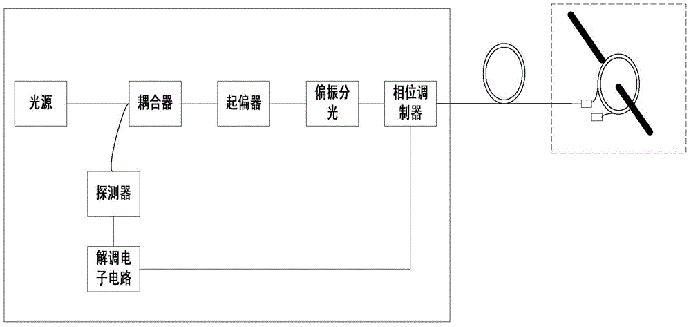
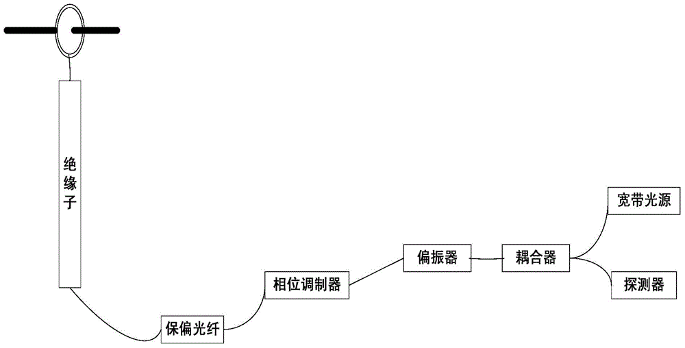
[0027] Examples, see Figure 1 to Figure 3 Shown:

[0028] The all-fiber-optic current transformer detection system provided in this embodiment includes a sensing fiber ring, an optical system, a circuit system and a merging unit;

[0029] The sensing optical fiber ring is used to obtain the current signal at the place to be measured and generate the light intensity signal to carry the data information of the Faraday optical rotation angle; the optical system is used to transmit the data information to the circuit system through an optical fiber; the circuit system The method is used to receive the data information transmitted by the optical system and convert it into a circuit digital signal; the merging unit is used to receive the circuit digital signal generated by the circuit system and output an identificat...


PUM


Abstract

The invention discloses an all-fiber optical current transformer detection system. The all-fiber optical current transformer detection system comprises a sensing optical fiber ring, a light path system, a circuit system and a merging unit; the sensing optical fiber ring is used for acquiring a current signal of a to-be-detected position and generating a light intensity signal carrying data information of a Faraday rotation angle; the light path system is used for transmitting the data information to the circuit system by virtue of the optical fiber; the circuit system is used for receiving data information transmitted by the light path system and converting the data information to a circuit digital signal; the merging unit is used for receiving the circuit digital signal generated by the circuit system and outputting an identification signal. The current transformer adopts a special optical fiber winding way, so that the temperature drift can be effectively inhibited, the influence of the birefringence phenomenon on detection precision of an ordinary optical fiber transformer can be overcome, the birefringence phenomenon is influenced by the temperature, so that the precision drift of the detection precision caused along with the temperature variation exists.

Description

technical field [0001] The invention relates to the field of intelligent detection of power grids, in particular to an all-optical fiber current transformer detection system. Background technique [0002] With the rapid development of the smart grid, the current transformer, one of the basic core equipment, has also ushered in a period of rapid development. In addition to being used in smart grids, current transformers have also been successfully used in many industrial fields such as ship electrical systems, grid traveling wave distance measurement, high-voltage DC power transmission, DC ice melting, power quality monitoring, etc., to achieve current and voltage-based Measurement applications of various electrical parameters. At present, it is being widely used in the fields of the highest voltage level of 1000kV in my country, new energy grid-connected flexible DC power transmission, rail transit power, and thermonuclear fusion international cooperation large scientific p...

Claims


Application Information

Patent Timeline
IPC IPC(8): G01R15/24
Inventor 王彬栩安磊方伟王飞军管金胜叶斌赵剑陈毅杰
Owner 宁波永耀信息科技有限公司
Learn More