A switch circuit with zero power consumption in standby state

A switching circuit, standby state technology, applied in electronic switches, electrical components, pulse technology and other directions, can solve problems such as unfavorable handheld equipment use, cumbersome operation, circuit can not work, etc., to achieve convenient size and appearance requirements, simple and convenient operation , the effect of small operating current

Active Publication Date: 2018-02-09
于红勇
View PDF7 Cites 0 Cited by
  • Summary
  • Abstract
  • Description
  • Claims
  • Application Information

AI Technical Summary

Problems solved by technology

One is the capacitance value of the capacitor, which determines how long the system can still work normally after power off. The larger the capacitance value, the longer it can last, but the larger the capacitance value, the larger the capacitor itself, which is not conducive to equipment miniaturization and handheld use of equipment
The second is that the capacitance value of the capacitor will decay over time, so the longer this circuit lasts, the less reliable the work will be.
The third is that the work depends on the charging capacitor. If it is used for the first time or if it is not used for a long time, the capacitor will have no power and the circuit will not work. You must use another button to charge the capacitor, which is cumbersome to operate.
[0004] The invention patent application with the application number 201110062826.7 discloses a zero-power standby circuit, which is not a real zero-power consumption, because the infrared receiving and decoding part needs to be powered all the time to work in the standby mode, and the infrared receiving and decoding part itself is the power supply. source of consumption

Method used


Image

  • A switch circuit with zero power consumption in standby state
  • A switch circuit with zero power consumption in standby state
  • A switch circuit with zero power consumption in standby state

Examples


Embodiment 1

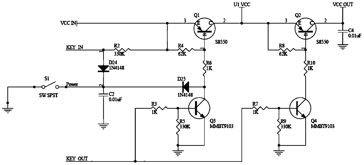
[0023] Such as figure 1 , Figure 4 As shown, a switch circuit with zero power consumption in the standby state includes a first triode Q1, a second triode Q2, a third triode Q3, and a fourth triode Q4. The transistor Q1 and the second transistor Q2 are PNP transistors, the third transistor Q3 and the fourth transistor Q4 are NPN transistors,

[0024] The input terminal VCC IN of the main power supply is connected to the emitter of the first triode Q1, and the fourth resistor R4 which acts as a bias is connected between the input terminal of the main power supply and the base of the first triode Q1. The collector of the transistor Q1 is connected to the emitter of the second triode Q2, and the eighth resistor R8 which acts as a bias is connected between the collector of the first transistor Q1 and the base of the second transistor Q2. The collector of the transistor Q2 is used as the output terminal of the switch circuit;

[0025] The collector of the first triode Q1 is con...

Embodiment 2

[0039] The difference between this embodiment and Embodiment 1 is that the emitter of the second transistor Q2 and the eighth resistor R8 are disconnected from the collector of the first transistor Q1 and directly connected to the input terminal VCC IN of the main power supply. Above, others are consistent with Embodiment 1. This embodiment skips the first triode Q1 by skipping the power-taking position of the output terminal VCC OUT of the switch circuit, and directly takes power from the input terminal VCC IN of the main power supply. If it is large Current working circuits can use this circuit, which minimizes the current consumption on the circuit.

Embodiment 3

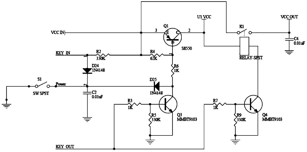
[0041] The difference between this embodiment and the above two embodiments is that the second triode Q2 is replaced by a relay, and the control coil of the relay is connected to the collector of the first triode Q1 and the fourth triode Between the collectors of Q4, the switch K1 controlled by the relay control coil is connected between the input terminal VCC IN of the main power supply and the output terminal VCC OUT of the switch circuit, and the others are consistent with the above embodiments. In this embodiment, a relay is used as a circuit for taking power from the system, which can be expanded and used in industrial high-current or high-voltage fields.

[0042] Preferably, the second triode can also be replaced with other controllable electronic components such as field effect transistors or photocouplers, and the control connection methods thereof are well known to those skilled in the art.


PUM


Abstract

The invention discloses a switch circuit with zero power consumption in a standby state, comprising a PNP-type first transistor and a second transistor, an NPN-type third transistor and a fourth transistor, and a main power supply The input end of the first triode is connected to the emitter of the first triode, the fourth resistor is connected between the input end of the main power supply and the base of the first triode, and the collector of the first triode is connected to the emitter of the second triode. The eighth resistor is connected between the collector of the first triode and the base of the second triode; the collector of the first triode is also connected with the power input terminal of the microcontroller, and the diode at the signal input terminal of the microcontroller is connected to the switch The start switch of the power supply is connected, and the signal input terminal is also connected to the input terminal of the main power supply through the second resistor; the signal output terminal of the microcontroller is connected to the bases of the third triode and the fourth triode respectively, and the third triode The collector of the tube is connected to the base of the first triode, the collector of the third triode is connected to start the switch, and the collector of the fourth triode is connected to the base of the second triode.

Description

technical field [0001] The invention relates to a switch circuit, in particular to a switch circuit with zero power consumption in a standby state. Background technique [0002] In some electrical equipment, in order to save power when the equipment is not working, it is often necessary to manually pull out the main power switch of the equipment, so that the equipment does not consume power in the standby state and reduce potential safety hazards. However, once the equipment needs to be re-enabled At this time, it is necessary to manually turn on or plug in the main power plug. Cause unnecessary trouble, and can make the service life of equipment reduce. Therefore, switching circuits are often used in practical applications to automatically turn off and start the main power supply of equipment, but the existing switching circuits do not achieve true zero power consumption. [0003] The authorized announcement number is: CN201918935U utility model patent and application num...

Claims


Application Information

Patent Timeline
Patent Type & Authority Patents(China)
IPC IPC(8): H03K17/96
Inventor 于红勇
Owner 于红勇
Why Eureka
Try Eureka