
Method for estimating the speed of an engine at a predetermined location

一种发动机速度、预定位置的技术,应用在估计发动机在预定位置的速度,内燃发动机领域

Active Publication Date: 2018-07-03
VTESCO TECH GMBH
View PDF6 Cites 0 Cited by
  • Summary
  • Abstract
  • Description
  • Claims
  • Application Information

AI Technical Summary

Problems solved by technology

The literature thus constrains the estimate to be within the measurement window w

Method used


Image

  • Method for estimating the speed of an engine at a predetermined location
  • Method for estimating the speed of an engine at a predetermined location
  • Method for estimating the speed of an engine at a predetermined location

Examples


Embodiment Construction

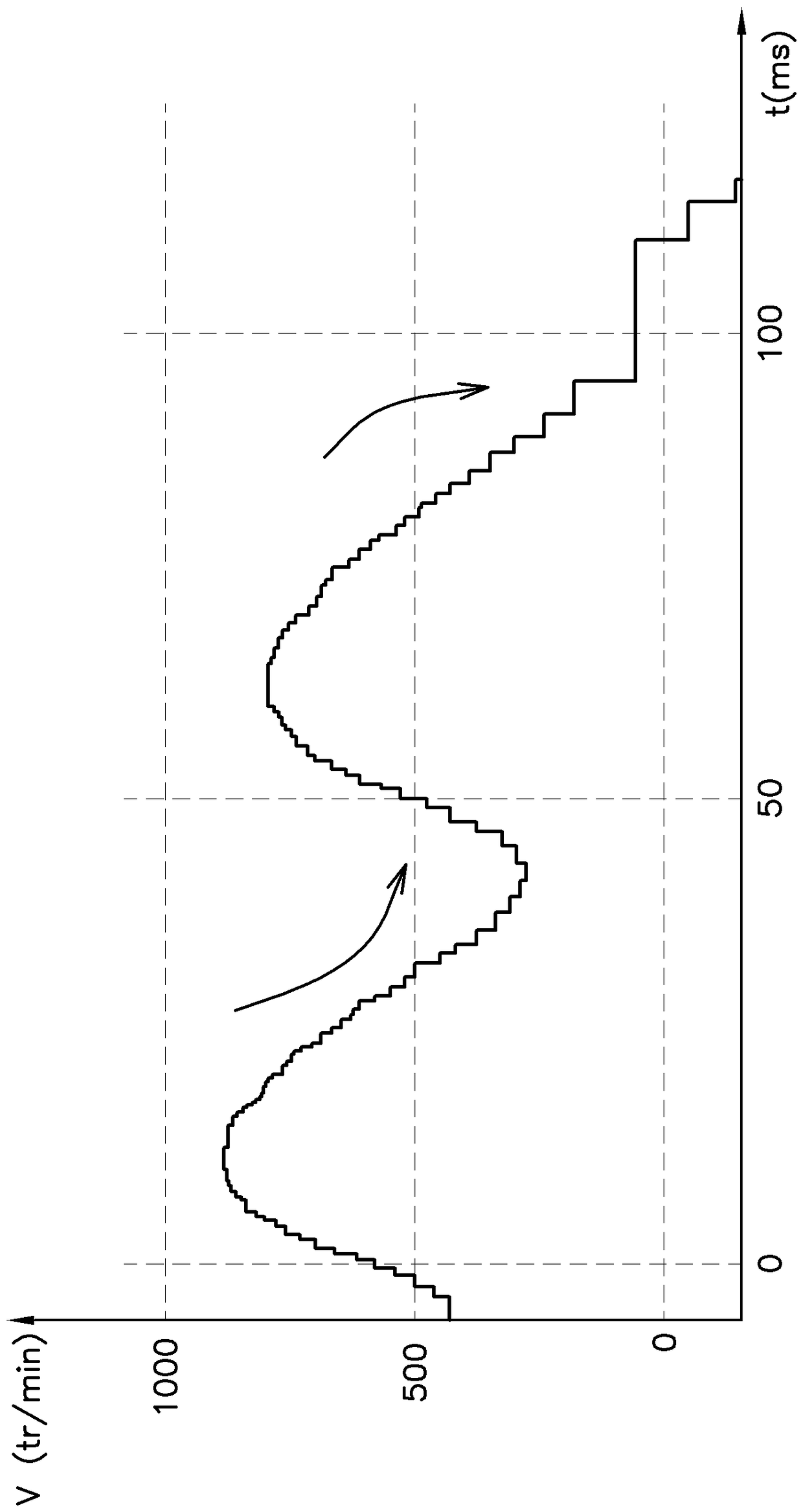
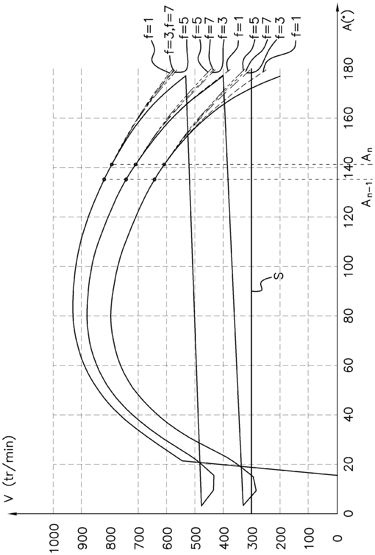
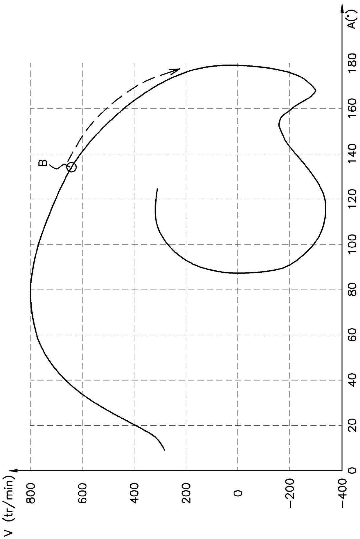
[0046]This description relates to diesel or spark ignition (Otto) internal combustion engines. Conventionally, such engines include an engine block in which is a machined cylinder closed at one end thereof by a cylinder head. The cylinder contains a piston linked to a crankshaft by means of a piston rod. A flywheel is mounted on one end of the crankshaft. The position of the crankshaft determines the position of the engine, ie if this position is known, the positions of all the pistons in the corresponding cylinders and the positions of many other mechanical parts of the engine are also known. Since the crankshaft does not have any rotational degrees of freedom, the position of the engine therefore depends on an angular value called the (angular) position of the engine. Furthermore, it is assumed in the remainder of this description that the engine concerned has a four-stroke cycle. Thus, once the crankshaft has completed two revolutions for each cylinder, a complete combus...


PUM


Abstract

The method comprises the steps of: - determining the angular position and the rotational velocity for the first and the second measuring point of the motor position sensor, - determining the rotational velocity in addition to the velocity gradient between the two measuring points in the previous step at least one gradient of velocity, -approximating the true curve of rotational velocity versus angular position using a polynomial function of degree 2, and -calculating in advance an estimated rotational velocity at a predetermined position by applying a polynomial function at said predetermined future position, the The predetermined position is a future angular position of the crankshaft. Apply the prediction of reverse rotation of the engine.

Description

technical field [0001] The invention relates to a method for estimating the speed of an engine at a predetermined position, more specifically, with the aim of determining in advance the risk of a reversal of the direction of rotation of said engine. [0002] The present invention relates generally to internal combustion engines, and more particularly to such engines in motor vehicles. Background technique [0003] Whether a spark ignition engine (Otto engine) or a compression ignition engine (diesel engine), internal combustion engines generally operate in a single direction of rotation. However, when the engine is stopped, the engine turns in one direction and then the other in an oscillating movement about its rest position before reaching its rest position. [0004] Detecting a reversal in the direction of rotation of an engine has become useful due to the development of systems commonly referred to as "stop and start" systems. In fact, it is important to determine the ...

Claims


Application Information

Patent Timeline
Patent Type & Authority Patents(China)
IPC IPC(8): F02D41/00F02D41/24G01P3/44G01P13/04
CPCF02D41/009F02D41/0097F02D41/042F02D41/2416F02N11/0844G01P3/44G01P13/045F02D2200/101F02D2200/1012F02N2200/022F02N2250/04F02N2300/2006F02D41/00G01D5/00G01P3/00
Inventor B.马科纳托
Owner VTESCO TECH GMBH
Features
  • Generate Ideas
  • Intellectual Property
  • Life Sciences
  • Materials
  • Tech Scout
  • Unparalleled Data Quality
  • Higher Quality Content
  • 60% Fewer Hallucinations
Learn More