Compound plastic forming equipment, die transposition mechanism thereof and positioning method for die transposition mechanism

A plastic forming and mold technology, applied in other manufacturing equipment/tools, forming tools, metal processing equipment, etc., can solve the problems of unstable quality, affecting product accuracy, unreliability, etc., to improve manufacturing accuracy and product quality, improve The effect of product accuracy and prolonging service life

Active Publication Date: 2015-05-27
江苏宗颐新材料科技有限公司
View PDF12 Cites 13 Cited by
  • Summary
  • Abstract
  • Description
  • Claims
  • Application Information

AI Technical Summary

Problems solved by technology

This invention has the function of transposition, but the convex and concave molds of the mold transposition mechanism can only be guided by the die mouth of the concave mold, and do not have the positioning function, and there is a gap in the guiding part of the convex and concave molds, so the positioning accuracy is not high, which affects the quality of the product; In addition, there is a gap between the tracks of the mold transposition mechanism, and the punch will produce a small amount of inclination when it is working under force, which will also affect the precision of the product and cause u

Method used


Image

  • Compound plastic forming equipment, die transposition mechanism thereof and positioning method for die transposition mechanism
  • Compound plastic forming equipment, die transposition mechanism thereof and positioning method for die transposition mechanism
  • Compound plastic forming equipment, die transposition mechanism thereof and positioning method for die transposition mechanism

Examples


Embodiment Construction

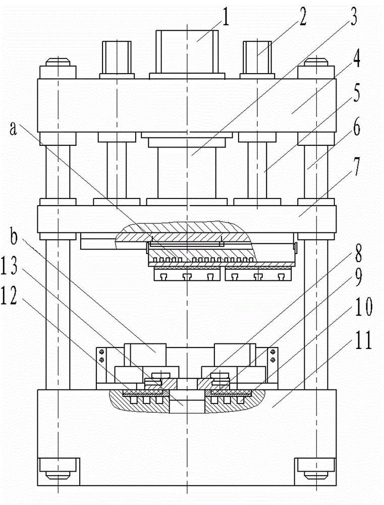
[0033] An example of composite plastic forming equipment in the present invention is Figure 1~Figure 11 As shown, it is a compound extrusion forming equipment for automobile hub, which adopts the basic frame of common hydroforming equipment, such as figure 1 As shown, its main structure includes a column 6, an upper beam 4 fixedly arranged on the upper and lower ends of the column 6, a lower beam 11 and a movable beam 7 slidingly matched with the column 6, and the upper beam 4 is fixedly provided with a main cylinder 1 and an auxiliary cylinder. 2. Two auxiliary cylinders 2 are arranged symmetrically on both sides of the main cylinder 1 in the radial direction. The main cylinder piston 3 of the main cylinder 1 and the auxiliary cylinder piston 5 of the auxiliary cylinder 2 are both connected to the movable beam 7 for driving the movable beam 7 up and down. sports.

[0034] An upper mold assembly and a lower mold assembly are respectively arranged on the movable beam 7 and th...


PUM


Abstract

The invention relates to compound plastic forming equipment, a die transposition mechanism thereof and a positioning method for the die transposition mechanism. The compound plastic forming equipment comprises the die transposition mechanism; the die transposition mechanism comprises a fixed part and a movable part which is in director motion relative to the fixed part; a positioning device used for enabling the fixed part and the movable part to be positioned along the direction of the director motion is arranged between the fixed part and the movable part, and a locking device used for enabling the fixed part and the movable part to be in force fit along the jacking direction of a die is also arranged between the fixed part and the movable part; the movable part can be positioned on the fixed part along the direction of the director motion through the positioning device, so the positioning accuracy in the direction of the director motion is improved; the movable part and the fixed part can be in force fit along the jacking direction of the die through the locking device, so the die can be prevented from inclining during die assembly, and while the product accuracy is improved, the phenomenon that positioning is inaccurate due to the fact that the die inclines during the die assembly under the condition that the die is only positioned by the positioning device can be avoided, and the manufacturing accuracy and the product quality can be helped to increase.

Description

technical field [0001] The invention relates to composite plastic forming equipment, a mold transposition mechanism and a positioning method for the mechanism. Background technique [0002] At present, light alloy automobile wheels mainly include aluminum alloy wheels and magnesium alloy wheels. Aluminum alloy has the characteristics of light weight, anti-corrosion, good thermal conductivity, etc., and its forming process is relatively good. It is being widely used in modern automobile manufacturing instead of steel wheels. Magnesium alloy material has low density, high specific strength and specific stiffness, and has high vibration damping and impact resistance, which is more suitable for the use conditions of the wheel hub. [0003] The Chinese invention patent specification with the patent number of 2009100643359 discloses a two-step plastic forming method for automobile wheels. In the extrusion molding mold, the spoke part is first formed by extrusion and the front an...

Claims


Application Information

Patent Timeline
IPC IPC(8): B23P23/00B21C23/21B21C25/02B21D37/10B21D53/26
CPCB21C23/21B21C25/02B21D53/268B23P23/00
Inventor 虞跨海杨永顺杨茜李辉郭俊卿陈拂晓
Owner 江苏宗颐新材料科技有限公司
Why Eureka
Try Eureka