Extrusion device

An extrusion device and packaged technology, which is applied in the field of extrusion devices, can solve the problems of little effect of dispersion and mixing, increased difficulty and cost of screw processing, and low energy utilization rate, so as to realize the effect of stretching and reorientation, increase Solid conveying efficiency, the effect of improving the effective utilization rate

Active Publication Date: 2015-05-27
李建钢
View PDF6 Cites 5 Cited by
  • Summary
  • Abstract
  • Description
  • Claims
  • Application Information

AI Technical Summary

Problems solved by technology

Although the emergence of twin-screw and multi-screw extruders can improve the mixing and mixing effect to a certain extent, generally speaking, the existing equipment has five major defects: (1) the mixing and mixing effect is poor; (2) the melting process is long and Uneven; (3) high energy consumption and low energy utilization rate; (4) low specific output; (5) narrow adaptability to processed materials, and time-consuming and laborious replacement of structural components
[0009] South Korean researchers Kim and Kwon proposed a technical scheme of inserting intermittent short flight in a single screw along the development direction of the screw groove to introduce periodic hyperbolic point disturbance, and proposed the concept of chaotic screw. Under the large situation, the mixing effect of polymer melt has been improved; But there is still certain technical defect in this chaotic flip-flop of short flight: (1) Disturbance is discontinuous: be provided with the screw screw disturbance of discontinuous short flight is discontinuous It is only at the discontinuity of the short screw edge as the trigger of chaos that the mixing will be greatly improved, but this will inevitably lead to increased power consumption and lack of continuous dynamics thinking; (2) Difficult to process: as a trigger of chaos The short flight of the device is fixed with the screw, which is similar to the structure of a double-ended screw, which increases the difficulty and cost of screw processing; (3) the improvement of mixing is local, and the dispersion and mixing effect is poor: the short as a trigger of chaos There is no relative movement between the screw edge and the screw channel, which has little effect on the improvement of dispersion mixing, resulting in the mixing effect at the bottom of the screw channel even worse than that of the traditional single-screw extruder, so the improvement of the mixing process is passive, partial and limited

Method used


Image

  • Extrusion device
  • Extrusion device
  • Extrusion device

Examples


Embodiment 1

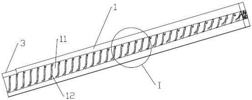
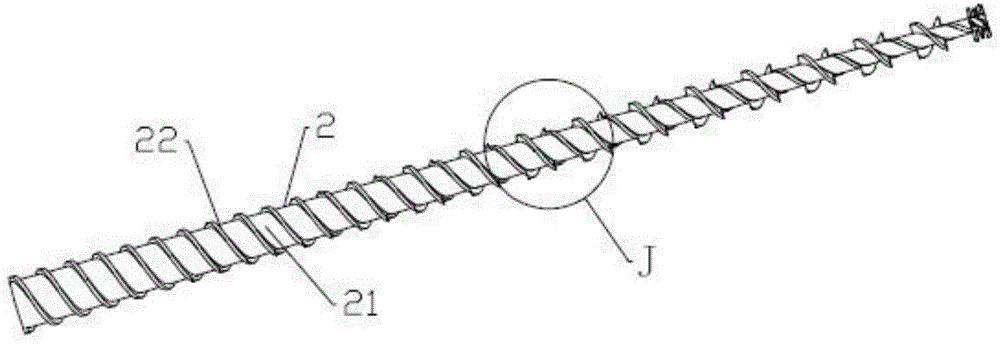
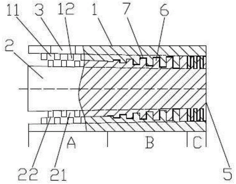
[0048] Extrusion device of the present embodiment such as Figures 1 to 8 , 19, and 20, including a barrel 1 and a screw 2 set in the barrel 1, the top wall of the front end of the barrel 1 is provided with a feed port 3, and the tail end of the barrel 1 is provided with a discharge port 5 , the inner wall of the barrel 1 is provided with a first screw groove 11, the inner wall of the barrel 1 forms a first screw edge 12, the screw groove of the outer wall of the screw rod 2 is a second screw groove 21, and the outer wall of the screw rod 2 The screw edge is the second screw edge 22, and the helical direction of the first screw groove 11 and the second screw groove 21 is opposite. The extruder includes a feeding section A and a first-order screw section, and the first-order screw section includes a The first-stage compression section B and the first-stage homogenization section C, the feeding section A is located at the front end of the first-stage compression section B, the f...

Embodiment 2

[0052] The difference between the extruding device of this implementation and embodiment 1 is: as Figure 9 As shown, the extrusion device has only a first-stage screw section, and the feeding section A is cancelled. The first-stage screw section includes a first-stage compression section B and a first-stage homogenization section C, and the first-stage homogenization section C is located in the first-stage compression section. At the tail end of B, the feed port 3 is located at the top of the side wall of the front end of the barrel 1 corresponding to the first-stage homogenization section C.

Embodiment 3

[0054] The extrusion device of this implementation is to increase the second-stage screw section and exhaust section D on the basis of Example 1, such as Figures 10 to 20As shown, the second-stage screw section is located behind the first-stage screw section, the exhaust section D is located between the first-stage screw section and the second-stage screw section, and an exhaust port is opened at the top of the side wall of the barrel 1 corresponding to the exhaust section D 4. The inner wall of the barrel 1 corresponding to the exhaust section D is not provided with the first screw groove 11, that is, the inner wall of the barrel 1 corresponding to the exhaust section D has no first screw edge 12, and the screw 2 corresponds to the exhaust section A small gap is kept between the second flight 22 of D and the inner wall of the barrel 1 to avoid friction between the second flight 22 of this section of the screw 2 and the inner wall of the barrel 1, so as to ensure that the scre...


PUM


Abstract

The invention discloses an extrusion device. The extrusion device comprises a material barrel and a screw rod sleeved by the barrel; a material inlet and a material outlet are arranged on wall of the material barrel; a first screw groove is arranged on inner side wall of the material barrel to form a first screw ridge and a second screw groove is arranged on outer side wall of the screw rod to form a second screw ridge, wherein the first screw groove and the second crew groove are opposite in spiral directions; the extrusion device also comprises a one-step screw rod section; the material inlet is located on the side wall of the material barrel and at a position corresponding to a front end or the front of the one-step screw rod section; the material outlet is located on the side wall of the material barrel and at a position corresponding to a rear end or the back of the one-step screw rod section; the first screw ridge and the second screw ridge corresponding to the one-step screw rod section are in cross matching along screw ridge directions to form an annular pulse peak and valley structure, wherein the screw ridges in raised parts of the first and second screw ridges are screw ridge peaks while the screw ridges in sunk parts are screw ridge valleys; the screw ridge peak of the first screw ridge can be matched with the screw ridge valley of the second screw ridge and the screw ridge peak of the second screw ridge can be matched with the screw ridge valley of the first screw ridge. The extrusion device has the advantages such as short material residence time, strong processing capability and good dispersive mixing and distributive mixing effects.

Description

technical field [0001] The invention relates to the field of screw mixing and extrusion, in particular to an extrusion device. Background technique [0002] At present, the equipment with screw is widely used in industrial occasions such as petroleum, chemical industry, household appliances, food processing, polymer filling modification and reaction extrusion. Existing belt screw devices mainly include single-screw extruders, twin-screw extruders and multi-screw extruders. Among them, the twin-screw extruder can be further divided into co-rotating, counter-rotating, meshing, non-meshing forms, staggered, parallel and other forms. Although the emergence of twin-screw and multi-screw extruders can improve the mixing and mixing effect to a certain extent, generally speaking, the existing equipment has five major defects: (1) the mixing and mixing effect is poor; (2) the melting process is long and Uneven; (3) high energy consumption and low energy utilization; (4) low specifi...

Claims


Application Information

Patent Timeline
Patent Type & Authority Applications(China)
IPC IPC(8): B29C47/38B29C47/60B29C47/66B29C48/68B29C48/395
CPCB29C48/395B29C48/68
Inventor 李建钢
Owner 李建钢
Why Eureka
Try Eureka