Variable radius spiral spillway
A flood discharge tunnel and variable radius technology, which is applied in the field of flood discharge tunnels with high hydraulic parameters, can solve the problems of high flow velocity at the tail of the tunnel and water outlet, difficult energy dissipation in the downstream arrangement, and easy damage to the flood discharge and energy dissipation facilities. The length of the hole, the effect of improving the economics of the project and shortening the construction period
- Summary
- Abstract
- Description
- Claims
- Application Information
AI Technical Summary
Problems solved by technology
Method used
Image
Examples
Embodiment 1
[0029] The engineering overview of embodiment 1 and comparative example 1 is as follows:
[0030] A power station is built in a V-shaped valley, with steep mountains on both sides and complex geological and topographical conditions. It is required that the entrance elevation of the flood discharge tunnel is 1061m, the exit elevation is 951m, the drop is 110m, and the flood discharge flow is 420m 3 / s.
[0031] Aiming at the above-mentioned projects, hydraulic model tests of two kinds of spillway tunnel layouts in Example 1 and Comparative Example 1 were carried out.
[0032] Example 1
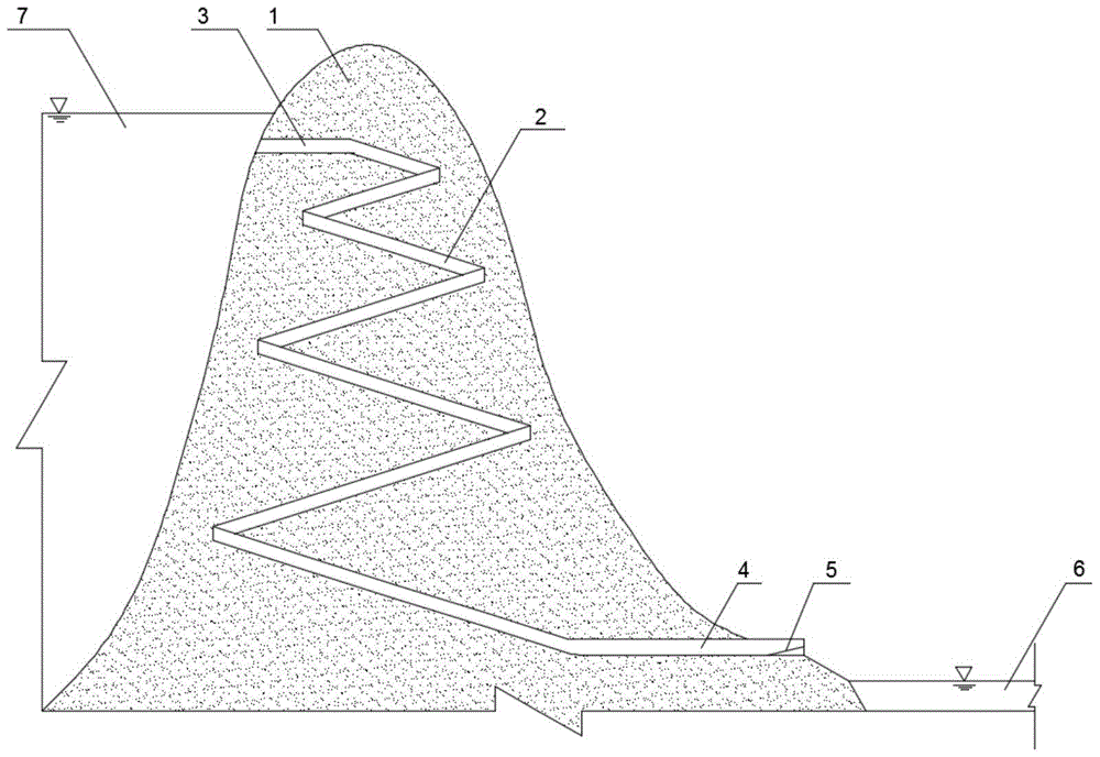
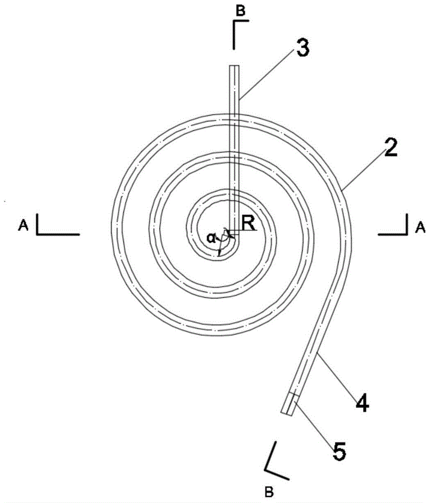
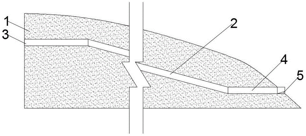
[0033] In this embodiment, a spiral flood discharge tunnel with variable radius is used, and the structure is as follows figure 1 , 2 , 3, and 4, the variable radius spiral flood discharge tunnel 2 is arranged in the mountain body 1 on the side of the reservoir dam, the upstream end of the variable radius spiral flood discharge tunnel is located at the top of the mountain body 1, and the dow...
Embodiment 2
[0038] The engineering overview of embodiment 2 and comparative example 2 is as follows:
[0039] A power station is built in a V-shaped valley, with steep mountains on both banks and a narrow and wide mountain downstream. The entrance elevation of the flood discharge tunnel is 746m, the exit elevation is 606m, the drop is 140m, and the flood discharge flow is 300m 3 / s. Aiming at the above-mentioned projects, hydraulic model tests of two kinds of flood discharge facility layouts in Example 2 and Comparative Example 2 were carried out.
[0040] Example 2
[0041] In this embodiment, a spiral flood discharge tunnel with variable radius is used, and the structure is as follows figure 1 , 2, 3, and 4, the variable radius spiral flood discharge tunnel 2 is arranged in the mountain body 1 on the side of the reservoir dam, the upstream end of the variable radius spiral flood discharge tunnel is located at the top of the mountain body 1, and the downstream end is located at the bo...
Embodiment 3
[0046] The engineering overview of embodiment 3 and comparative example 3 is as follows:
[0047] A power station is built in a narrow river valley, with steep mountains on both sides and deep river coverage in the downstream. The entrance elevation of the flood discharge tunnel is 861m, the exit elevation is 701m, the drop is 160m, and the flood discharge flow is 600m 3 / s. Aiming at the above-mentioned projects, the hydraulic model tests of two kinds of spillway tunnel layouts in Example 3 and Comparative Example 3 were carried out.
[0048] Example 3
[0049] In this embodiment, a spiral flood discharge tunnel with variable radius is used, and the structure is as follows figure 1 , 2 , 3, and 4, the variable radius spiral flood discharge tunnel 2 is arranged in the mountain body 1 on the side of the reservoir dam, the upstream end of the variable radius spiral flood discharge tunnel is located at the top of the mountain body 1, and the downstream end is located at the bo...
PUM
 Abstract
Description
Claims
Application Information
 - R&D
- Intellectual Property
- Life Sciences
- Materials
- Tech Scout
- Unparalleled Data Quality
- Higher Quality Content
- 60% Fewer Hallucinations
Browse by: Latest US Patents, China's latest patents, Technical Efficacy Thesaurus, Application Domain, Technology Topic, Popular Technical Reports.
© 2025 PatSnap. All rights reserved.Legal|Privacy policy|Modern Slavery Act Transparency Statement|Sitemap|About US| Contact US: help@patsnap.com


